User login
Recurrent Patellar Tendon Rupture in a Patient After Intramedullary Nailing of the Tibia: Reconstruction Using an Achilles Tendon Allograft
Ruptures of the patellar tendon usually occur in patients under age 40 years, with men having a higher incidence than women.1 History of local steroid injection,2,3 total knee arthroplasty,4-8 anterior cruciate ligament reconstruction with central third patellar tendon autograft,9-11 and a variety of systemic diseases are associated with an increased tendency to rupture.12-15 Primary acute ruptures of the patellar tendon can be difficult to repair because of the quality of remaining tissues. In cases of chronic tendon ruptures subject to delayed treatment, additional complications such as tissue contracture and scar-tissue formation are likely to exist.15-17
Complications after intramedullary (IM) nailing of the tibia include infection, compartment syndrome, deep vein thrombosis, thermal necrosis of the bone with alteration of its endosteal architecture, failure of the hardware, malunion, and nonunion.18 The most common complaint after IM nailing of the tibia is chronic anterior knee pain and symptoms similar to tendonitis; incidences as high as 86% have been reported.18-20 Extensive review of the literature found only 2 reports of patellar tendon rupture after IM nailing of the tibia; both cases used a patellar tendon–splitting approach. The first report described patellar tendon rupture 8 years after IM nailing of the tibia during a forced deep-flexion movement.21 Radiographic examination showed the IM nail positioned proud relative to the tibial plateau, impinging upon the patellar tendon. An intraoperative examination confirmed the radiographic findings and found rupture of the patellar tendon to be consistent with the exposed tip of the IM nail. The second report described patellar tendon rupture 2 months postoperatively in a patient with Ehlers-Danlos syndrome, a hereditary disorder characterized by alterations to muscle/tendon tissue and hyperextensible skin.22
Patellar tendon rupture after IM nailing of the tibia is a rare complication. Patellar tendon re-rupture after primary repair in a patient with history of IM tibial nailing has not been reported. This case outlines the progression of such a patient with a recurrent patellar tendon rupture that was successfully reconstructed using an Achilles tendon allograft. The patient’s surgical history of IM tibial nailing through a mid-patellar tendon–splitting approach 4 years prior to initial tendon rupture is noteworthy and potentially predisposed the patient to injury. The patient provided written informed consent for print and electronic publication of this case report.
Case Report
A 44-year-old woman, 5 ft, 3 in tall, and weighing 129 lb (body mass index, 22.8), with a history of osteoporosis and transverse myelitis, presented with pain and persistent swelling about the left knee. Her baseline ambulatory status required crutches because of decreased sensation and strength in her lower extremity in conjunction with a foot drop; she had mild quadriceps and hamstring muscle weakness but otherwise normal knee function. The patient had been seen 4 years earlier at our facility for IM fixation of a distal tibia fracture through a patellar tendon–splitting approach. The fracture was well healed and showed no signs of complication or nail migration; the nail was not proud.
Initially, the patient was admitted to another hospital through the emergency department for swelling and pain about the left knee. She was believed to have an infection and was placed on antibiotics by the primary care team. An orthopedic evaluation showed induration, edema, and warmth in the patellar tendon region of the left knee. Magnetic resonance imaging (MRI) showed a full-thickness patellar tendon rupture. Aspiration of the knee was performed and cultures were negative; white blood cell, erythrocyte sedimentation rate, and C-reactive protein values were normal. The risks and benefits of various treatments were discussed, and surgical intervention was elected to repair the patellar tendon.
Intraoperative findings showed a massive midsubstance rupture of the patellar tendon, accompanied by medial and lateral retinacular tears and a quadriceps tendon partial rupture; the central aspect of the quadriceps tendon attaching to the patella remained intact. The patella was retracted proximally; no evidence of active infection was present. Good-quality tissue remained attached to both the tibial tuberosity and the inferior pole of the patella. A No. 2 FiberWire suture (Arthrex, Inc, Naples, Florida) was used to run whip stitches in the distal end of the patellar tendon and a second No. 2 FiberWire suture was used to run whip stitches in the proximal aspect of the patellar tendon rupture. The 4 ends of the sutures were tied together, thus re-approximating the distal and proximal ends of the ruptured patellar tendon. No bone drilling was used because the midsubstance tear was amenable to good repair with reasonable expectation of healing based on tissue quality. The quadriceps tendon, which was partially torn, was repaired with a No. 1 Vicryl suture (Ethicon, Somerville, New Jersey). The medial and lateral retinacula were also repaired with a No. 1 Vicryl suture. The suturing scheme effectively re-approximated the knee extensor mechanism, and the patient was placed in a knee immobilizer that permitted no flexion for 6 weeks postoperatively.
After 3 months of gradual improvement with physical therapy, the patient returned for a follow-up visit, concerned that her knee function was beginning to decline. Physical examination showed patella alta with a thinned and diminutive palpable tendon in the patellar tendon region. She was capable of active flexion to 90º and extension to 50º, but beyond 50º, she was unable to actively extend; she was capable of full passive extension. MRI showed a repeat full-thickness patellar tendon tear with retraction from the inferior pole of the patella; previous tears to the quadriceps tendon were healed. Because of the recurrent nature of the injury, the patient’s physical examination, MRI findings, and anticipated poor quality of remaining tendon tissue, patellar tendon reconstruction using a cadaveric Achilles tendon allograft was recommended. The patient chose surgery for potential improvement in knee range of motion, active extension, and ambulation.
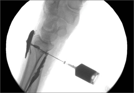
The previous anterior midline incision was used and carried down through the subcutaneous tissues where a complete rupture of the patellar tendon was identified. A limited amount of good-quality tendon tissue remained at the medial aspect of the tibial tuberosity. The remaining tissue located at the patella’s inferior pole was nonviable for use in surgical repair. Retinacular contractures were released to bring the patella distally; the trochlear groove was used as the anatomic landmark for the patella resting position. During reconstruction, the knee was placed into 30° of flexion, with the patella located in the trochlear groove, and the cadaveric Achilles tendon was placed on the midline of the patella, where measurements were done to assess proper length and tension (Figure 1).

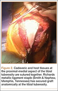
The patient’s remaining native tissue on the medial aspect of the tibial tuberosity was used to augment the Achilles tendon graft medially. The cadaveric Achilles tendon graft was primarily used to replace the central and lateral aspects of the patellar tendon. Additionally, the calcaneal bone segment at the end of the Achilles tendon graft was removed prior to use. Cadaveric and host tissues at the medial aspect of the tibial tuberosity were sutured together with a No. 1 Vicryl suture (Figure 2). The distal aspect of the cadaveric Achilles tendon was used to re-approximate the patient’s native patellar tendon insertion at the tibial tuberosity. To supplement the graft anchor, a Richards metallic ligament staple (Smith & Nephew, Memphis, Tennessee) was used to fix the distal aspect of the Achilles tendon graft into the tibial tuberosity.
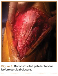
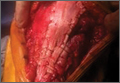
Proper tensioning of the graft was performed by visualizing patella tracking during the arc-of-knee motion and properly suturing the graft to allow for functional range. The proximal aspect of the cadaveric Achilles tendon was sutured into host tissues surrounding the superior pole of the patellar and quadriceps tendon. The edges of the graft were sutured with supplemental No. 1 Vicryl sutures (Figure 3).
Before surgical closure, knee range of motion was checked and noted to be 0º to 100º. The repaired construct was stable and uncompromised throughout the entire range of motion. Patella tracking was central and significantly improved; knee stability was normal to varus and valgus stress.
The patient was placed in a knee immobilizer for 6 weeks before range of motion was allowed. Seven months postoperatively, the patient returned for a follow-up visit, ambulating with 2 forearm crutches, which was her baseline ambulatory status. Physical examination revealed passive range of motion from 0º to 130º, an extension lag of 10º, and 4/5 quadriceps strength. It was recommended the patient continue physical therapy to improve strength and range of motion.
Conclusion
This is the first report in the literature documenting a recurrent patellar tendon rupture after primary repair in a patient with a history of IM tibial nailing. It is also the first report of a cadaveric Achilles tendon allograft used as a solution to this problem. Complete reconstruction of the patellar tendon using an Achilles tendon allograft is a method commonly used for ruptures after total knee arthroplasty.4-7,23,24 This case report highlights the utility of a cadaveric Achilles tendon in the setting of a recurrent patellar tendon rupture with poor remaining tissue quality.
1. Scott WN, Insall JN. Injuries of the knee. In: Rockwood CA Jr, Green DP, Bucholz RW, eds. Fractures in Adults. 3rd ed. Philadelphia, PA: JB Lippincott; 1991: 1799-1914.
2. Clark SC, Jones MW, Choudhury RR, Smith E. Bilateral patellar tendon rupture secondary to repeated local steroid injections. J Accid Emerg Med. 1995;12(4):300-301.
3. Unverferth LJ, Olix ML. The effect of local steroid injections on tendon. J Sports Med. 1973;1(4):31-37.
4. Cadambi A, Engh GA. Use of a semitendinosus tendon autogenous graft for rupture of the patellar ligament after total knee arthroplasty. A report of seven cases. J Bone Joint Surg Am. 1992;74(7):974-979.
5. Emerson RH Jr, Head WC, Malinin TI. Reconstruction of patellar tendon rupture after total knee arthroplasty with an extensor mechanism allograft. Clin Orthop.1990;(260):154-161.
6. Gustillo RB, Thompson R. Quadriceps and patellar tendon ruptures following total knee arthroplasty. In: Rand JA, Dorr LD, eds. Total Arthroplasty of the Knee: Proceedings of the Knee Society, 1985-1986. Rockville, MD: Aspen; 1987: 41-70.
7. Rand JA, Morrey BF, Bryan RS. Patellar tendon rupture after total knee arthroplasty. Clin Orthop. 1989;(244):233-238.
8. Schoderbek RJ, Brown TE, Mulhall KJ, et al. Extensor mechanism disruption after total knee arthroplasty. Clin Orthop. 2006;446:176-185.
9. Bonamo JJ, Krinik RM, Sporn AA. Rupture of the patellar ligament after use of the central third for anterior cruciate reconstruction. A report of two cases. J Bone Joint Surg Am. 1984;66(8):1294-1297.
10. Marumoto JM, Mitsunaga MM, Richardson AB, Medoff RJ, Mayfield GW. Late patellar tendon ruptures after removal of the central third for anterior cruciate ligament reconstruction. A report of two cases. Am J Sports Med. 1996;24(5):698-701.
11. Mickelsen PL, Morgan SJ, Johnson WA, Ferrari JD. Patellar tendon rupture 3 years after anterior cruciate ligament reconstruction with a central one third bone-patellar tendon-bone graft. Arthroscopy. 2001;17(6):648-652.
12. Morgan J, McCarty DJ. Tendon ruptures in patients with systemic lupus erythematosus treated with corticosteroids. Arthritis Rheum. 1974;17(6):1033-1036.
13. Webb LX, Toby EB. Bilateral rupture of the patellar tendon in an otherwise healthy male patient following minor trauma. J Trauma. 1986;26(11):1045-1048.
14. Greis PE, Holmstrom MC, Lahav A. Surgical treatment options for patella tendon rupture, Part I: Acute. Orthopedics. 2005;28(7):672-679.
15. Greis PE, Lahav A, Holstrom MC. Surgical treatment options for patella tendon rupture, part II: chronic. Orthopedics. 2005;28(8):765-769.
16. Lewis PB, Rue JP, Bach BR Jr. Chronic patellar tendon rupture: surgical reconstruction technique using 2 Achilles tendon allografts. J Knee Surg. 2008;21(12):130-135.
17. McNally PD, Marcelli EA. Achilles tendon allograft of a chronic patellar tendon rupture. Arthroscopy. 1998;14(3):340-344.
18. Katsoulis E, Court-Brown C, Giannoudis PV. Incidence and atieology of anterior knee pain after intramedullary nailing of the femur and tibia. J Bone Joint Surg Br. 2006;88(5):576-580.
19. Brumback RJ, Uwagie-Ero S, Lakatos RP, et al. Intramedullary nailing of femoral shaft fractures. Part II: Fracture-healing with static interlocking fixation. J Bone Joint Surg Am. 1988;70(1):1453-1462.
20. Koval KJ, Clapper MF, Brumback RJ, et al. Complications of reamed intramedullary nailing of the tibia. J Orthop Trauma. 1991;5(2):184-189.
21. Kretzler JE, Curtin SL, Wegner DA, Baumgaertner MR, Galloway MT. Patella tendon rupture: a late complication of a tibial nail. Orthopedics. 1995;18(11):1109-1111.
22. Moroney P, McCarthy T, Borton D. Patellar tendon rupture post reamed intra-medullary tibial nail in a patient with Ehlers-Danlos syndrome. A case report. Eur J Orthop Surg Traumatol. 2004;14(1):50-51.
23. Crossett LS, Sinha RK, Sechriest VF, Rubash HE. Reconstruction of a ruptured patellar tendon with achilles tendon allograft following total knee arthroplasty. J Bone Joint Surg Am. 2002;84(8):1354-1361.
24. Falconiero RP, Pallis MP. Chronic rupture of a patellar tendon: a technique for reconstruction with Achilles allograft. Arthroscopy. 1996;12(5):623-626.
Ruptures of the patellar tendon usually occur in patients under age 40 years, with men having a higher incidence than women.1 History of local steroid injection,2,3 total knee arthroplasty,4-8 anterior cruciate ligament reconstruction with central third patellar tendon autograft,9-11 and a variety of systemic diseases are associated with an increased tendency to rupture.12-15 Primary acute ruptures of the patellar tendon can be difficult to repair because of the quality of remaining tissues. In cases of chronic tendon ruptures subject to delayed treatment, additional complications such as tissue contracture and scar-tissue formation are likely to exist.15-17
Complications after intramedullary (IM) nailing of the tibia include infection, compartment syndrome, deep vein thrombosis, thermal necrosis of the bone with alteration of its endosteal architecture, failure of the hardware, malunion, and nonunion.18 The most common complaint after IM nailing of the tibia is chronic anterior knee pain and symptoms similar to tendonitis; incidences as high as 86% have been reported.18-20 Extensive review of the literature found only 2 reports of patellar tendon rupture after IM nailing of the tibia; both cases used a patellar tendon–splitting approach. The first report described patellar tendon rupture 8 years after IM nailing of the tibia during a forced deep-flexion movement.21 Radiographic examination showed the IM nail positioned proud relative to the tibial plateau, impinging upon the patellar tendon. An intraoperative examination confirmed the radiographic findings and found rupture of the patellar tendon to be consistent with the exposed tip of the IM nail. The second report described patellar tendon rupture 2 months postoperatively in a patient with Ehlers-Danlos syndrome, a hereditary disorder characterized by alterations to muscle/tendon tissue and hyperextensible skin.22
Patellar tendon rupture after IM nailing of the tibia is a rare complication. Patellar tendon re-rupture after primary repair in a patient with history of IM tibial nailing has not been reported. This case outlines the progression of such a patient with a recurrent patellar tendon rupture that was successfully reconstructed using an Achilles tendon allograft. The patient’s surgical history of IM tibial nailing through a mid-patellar tendon–splitting approach 4 years prior to initial tendon rupture is noteworthy and potentially predisposed the patient to injury. The patient provided written informed consent for print and electronic publication of this case report.
Case Report
A 44-year-old woman, 5 ft, 3 in tall, and weighing 129 lb (body mass index, 22.8), with a history of osteoporosis and transverse myelitis, presented with pain and persistent swelling about the left knee. Her baseline ambulatory status required crutches because of decreased sensation and strength in her lower extremity in conjunction with a foot drop; she had mild quadriceps and hamstring muscle weakness but otherwise normal knee function. The patient had been seen 4 years earlier at our facility for IM fixation of a distal tibia fracture through a patellar tendon–splitting approach. The fracture was well healed and showed no signs of complication or nail migration; the nail was not proud.
Initially, the patient was admitted to another hospital through the emergency department for swelling and pain about the left knee. She was believed to have an infection and was placed on antibiotics by the primary care team. An orthopedic evaluation showed induration, edema, and warmth in the patellar tendon region of the left knee. Magnetic resonance imaging (MRI) showed a full-thickness patellar tendon rupture. Aspiration of the knee was performed and cultures were negative; white blood cell, erythrocyte sedimentation rate, and C-reactive protein values were normal. The risks and benefits of various treatments were discussed, and surgical intervention was elected to repair the patellar tendon.
Intraoperative findings showed a massive midsubstance rupture of the patellar tendon, accompanied by medial and lateral retinacular tears and a quadriceps tendon partial rupture; the central aspect of the quadriceps tendon attaching to the patella remained intact. The patella was retracted proximally; no evidence of active infection was present. Good-quality tissue remained attached to both the tibial tuberosity and the inferior pole of the patella. A No. 2 FiberWire suture (Arthrex, Inc, Naples, Florida) was used to run whip stitches in the distal end of the patellar tendon and a second No. 2 FiberWire suture was used to run whip stitches in the proximal aspect of the patellar tendon rupture. The 4 ends of the sutures were tied together, thus re-approximating the distal and proximal ends of the ruptured patellar tendon. No bone drilling was used because the midsubstance tear was amenable to good repair with reasonable expectation of healing based on tissue quality. The quadriceps tendon, which was partially torn, was repaired with a No. 1 Vicryl suture (Ethicon, Somerville, New Jersey). The medial and lateral retinacula were also repaired with a No. 1 Vicryl suture. The suturing scheme effectively re-approximated the knee extensor mechanism, and the patient was placed in a knee immobilizer that permitted no flexion for 6 weeks postoperatively.
After 3 months of gradual improvement with physical therapy, the patient returned for a follow-up visit, concerned that her knee function was beginning to decline. Physical examination showed patella alta with a thinned and diminutive palpable tendon in the patellar tendon region. She was capable of active flexion to 90º and extension to 50º, but beyond 50º, she was unable to actively extend; she was capable of full passive extension. MRI showed a repeat full-thickness patellar tendon tear with retraction from the inferior pole of the patella; previous tears to the quadriceps tendon were healed. Because of the recurrent nature of the injury, the patient’s physical examination, MRI findings, and anticipated poor quality of remaining tendon tissue, patellar tendon reconstruction using a cadaveric Achilles tendon allograft was recommended. The patient chose surgery for potential improvement in knee range of motion, active extension, and ambulation.
The previous anterior midline incision was used and carried down through the subcutaneous tissues where a complete rupture of the patellar tendon was identified. A limited amount of good-quality tendon tissue remained at the medial aspect of the tibial tuberosity. The remaining tissue located at the patella’s inferior pole was nonviable for use in surgical repair. Retinacular contractures were released to bring the patella distally; the trochlear groove was used as the anatomic landmark for the patella resting position. During reconstruction, the knee was placed into 30° of flexion, with the patella located in the trochlear groove, and the cadaveric Achilles tendon was placed on the midline of the patella, where measurements were done to assess proper length and tension (Figure 1).
The patient’s remaining native tissue on the medial aspect of the tibial tuberosity was used to augment the Achilles tendon graft medially. The cadaveric Achilles tendon graft was primarily used to replace the central and lateral aspects of the patellar tendon. Additionally, the calcaneal bone segment at the end of the Achilles tendon graft was removed prior to use. Cadaveric and host tissues at the medial aspect of the tibial tuberosity were sutured together with a No. 1 Vicryl suture (Figure 2). The distal aspect of the cadaveric Achilles tendon was used to re-approximate the patient’s native patellar tendon insertion at the tibial tuberosity. To supplement the graft anchor, a Richards metallic ligament staple (Smith & Nephew, Memphis, Tennessee) was used to fix the distal aspect of the Achilles tendon graft into the tibial tuberosity.
Proper tensioning of the graft was performed by visualizing patella tracking during the arc-of-knee motion and properly suturing the graft to allow for functional range. The proximal aspect of the cadaveric Achilles tendon was sutured into host tissues surrounding the superior pole of the patellar and quadriceps tendon. The edges of the graft were sutured with supplemental No. 1 Vicryl sutures (Figure 3).
Before surgical closure, knee range of motion was checked and noted to be 0º to 100º. The repaired construct was stable and uncompromised throughout the entire range of motion. Patella tracking was central and significantly improved; knee stability was normal to varus and valgus stress.
The patient was placed in a knee immobilizer for 6 weeks before range of motion was allowed. Seven months postoperatively, the patient returned for a follow-up visit, ambulating with 2 forearm crutches, which was her baseline ambulatory status. Physical examination revealed passive range of motion from 0º to 130º, an extension lag of 10º, and 4/5 quadriceps strength. It was recommended the patient continue physical therapy to improve strength and range of motion.
Conclusion
This is the first report in the literature documenting a recurrent patellar tendon rupture after primary repair in a patient with a history of IM tibial nailing. It is also the first report of a cadaveric Achilles tendon allograft used as a solution to this problem. Complete reconstruction of the patellar tendon using an Achilles tendon allograft is a method commonly used for ruptures after total knee arthroplasty.4-7,23,24 This case report highlights the utility of a cadaveric Achilles tendon in the setting of a recurrent patellar tendon rupture with poor remaining tissue quality.
1. Scott WN, Insall JN. Injuries of the knee. In: Rockwood CA Jr, Green DP, Bucholz RW, eds. Fractures in Adults. 3rd ed. Philadelphia, PA: JB Lippincott; 1991: 1799-1914.
2. Clark SC, Jones MW, Choudhury RR, Smith E. Bilateral patellar tendon rupture secondary to repeated local steroid injections. J Accid Emerg Med. 1995;12(4):300-301.
3. Unverferth LJ, Olix ML. The effect of local steroid injections on tendon. J Sports Med. 1973;1(4):31-37.
4. Cadambi A, Engh GA. Use of a semitendinosus tendon autogenous graft for rupture of the patellar ligament after total knee arthroplasty. A report of seven cases. J Bone Joint Surg Am. 1992;74(7):974-979.
5. Emerson RH Jr, Head WC, Malinin TI. Reconstruction of patellar tendon rupture after total knee arthroplasty with an extensor mechanism allograft. Clin Orthop.1990;(260):154-161.
6. Gustillo RB, Thompson R. Quadriceps and patellar tendon ruptures following total knee arthroplasty. In: Rand JA, Dorr LD, eds. Total Arthroplasty of the Knee: Proceedings of the Knee Society, 1985-1986. Rockville, MD: Aspen; 1987: 41-70.
7. Rand JA, Morrey BF, Bryan RS. Patellar tendon rupture after total knee arthroplasty. Clin Orthop. 1989;(244):233-238.
8. Schoderbek RJ, Brown TE, Mulhall KJ, et al. Extensor mechanism disruption after total knee arthroplasty. Clin Orthop. 2006;446:176-185.
9. Bonamo JJ, Krinik RM, Sporn AA. Rupture of the patellar ligament after use of the central third for anterior cruciate reconstruction. A report of two cases. J Bone Joint Surg Am. 1984;66(8):1294-1297.
10. Marumoto JM, Mitsunaga MM, Richardson AB, Medoff RJ, Mayfield GW. Late patellar tendon ruptures after removal of the central third for anterior cruciate ligament reconstruction. A report of two cases. Am J Sports Med. 1996;24(5):698-701.
11. Mickelsen PL, Morgan SJ, Johnson WA, Ferrari JD. Patellar tendon rupture 3 years after anterior cruciate ligament reconstruction with a central one third bone-patellar tendon-bone graft. Arthroscopy. 2001;17(6):648-652.
12. Morgan J, McCarty DJ. Tendon ruptures in patients with systemic lupus erythematosus treated with corticosteroids. Arthritis Rheum. 1974;17(6):1033-1036.
13. Webb LX, Toby EB. Bilateral rupture of the patellar tendon in an otherwise healthy male patient following minor trauma. J Trauma. 1986;26(11):1045-1048.
14. Greis PE, Holmstrom MC, Lahav A. Surgical treatment options for patella tendon rupture, Part I: Acute. Orthopedics. 2005;28(7):672-679.
15. Greis PE, Lahav A, Holstrom MC. Surgical treatment options for patella tendon rupture, part II: chronic. Orthopedics. 2005;28(8):765-769.
16. Lewis PB, Rue JP, Bach BR Jr. Chronic patellar tendon rupture: surgical reconstruction technique using 2 Achilles tendon allografts. J Knee Surg. 2008;21(12):130-135.
17. McNally PD, Marcelli EA. Achilles tendon allograft of a chronic patellar tendon rupture. Arthroscopy. 1998;14(3):340-344.
18. Katsoulis E, Court-Brown C, Giannoudis PV. Incidence and atieology of anterior knee pain after intramedullary nailing of the femur and tibia. J Bone Joint Surg Br. 2006;88(5):576-580.
19. Brumback RJ, Uwagie-Ero S, Lakatos RP, et al. Intramedullary nailing of femoral shaft fractures. Part II: Fracture-healing with static interlocking fixation. J Bone Joint Surg Am. 1988;70(1):1453-1462.
20. Koval KJ, Clapper MF, Brumback RJ, et al. Complications of reamed intramedullary nailing of the tibia. J Orthop Trauma. 1991;5(2):184-189.
21. Kretzler JE, Curtin SL, Wegner DA, Baumgaertner MR, Galloway MT. Patella tendon rupture: a late complication of a tibial nail. Orthopedics. 1995;18(11):1109-1111.
22. Moroney P, McCarthy T, Borton D. Patellar tendon rupture post reamed intra-medullary tibial nail in a patient with Ehlers-Danlos syndrome. A case report. Eur J Orthop Surg Traumatol. 2004;14(1):50-51.
23. Crossett LS, Sinha RK, Sechriest VF, Rubash HE. Reconstruction of a ruptured patellar tendon with achilles tendon allograft following total knee arthroplasty. J Bone Joint Surg Am. 2002;84(8):1354-1361.
24. Falconiero RP, Pallis MP. Chronic rupture of a patellar tendon: a technique for reconstruction with Achilles allograft. Arthroscopy. 1996;12(5):623-626.
Emergency Imaging
Case
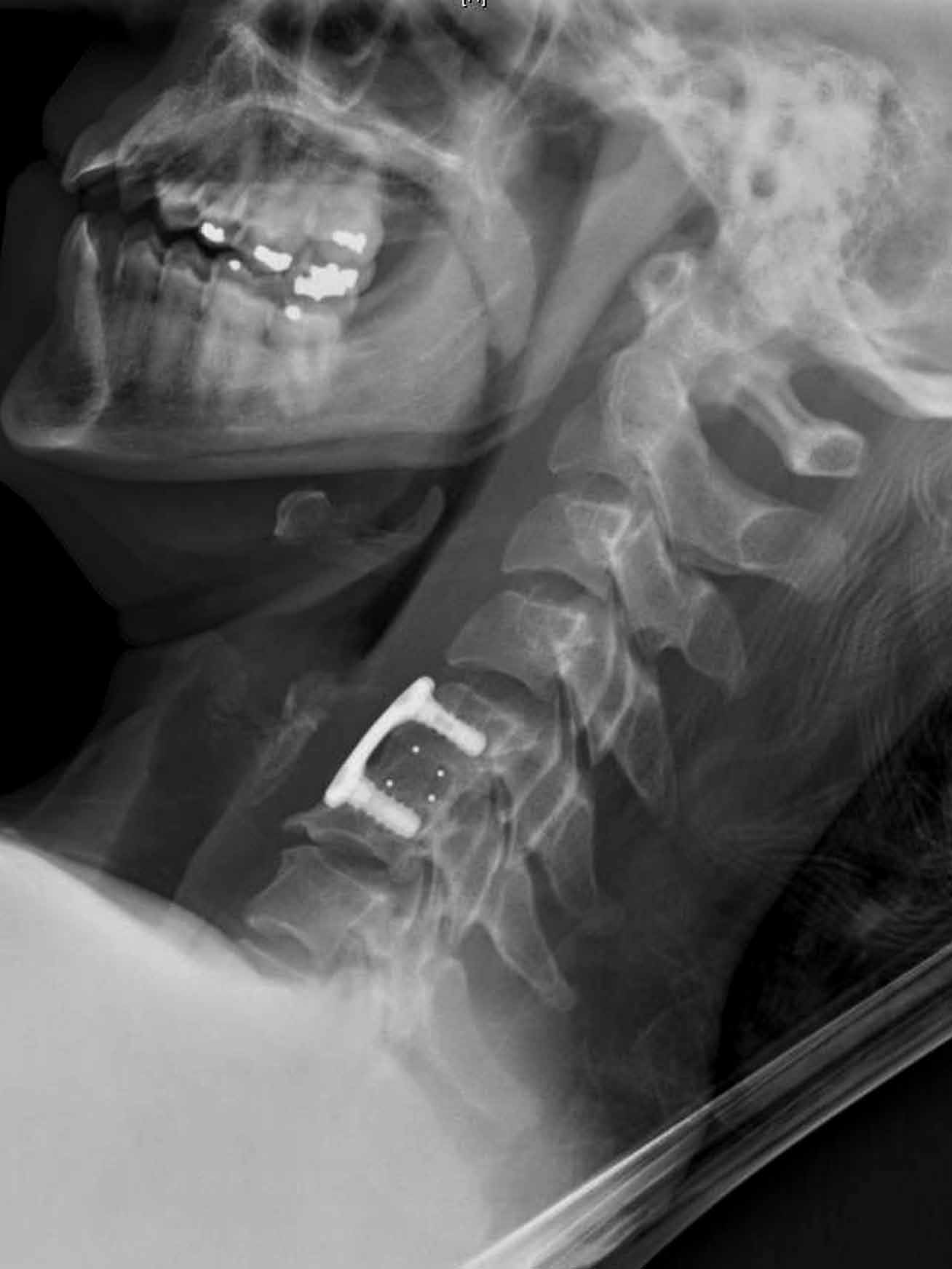
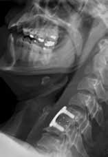
A 41-year-old woman presented to the ED with a 3-day history of posterior neck pain that radiated to the occipital region. The patient stated that the day prior to presentation, the pain had worsened to what she rated as a “9” on a pain scale of 0 to 10. The patient’s surgical history included a remote prior cervical fusion at C5-C6. A lateral radiograph of the cervical spine is shown above (Figure 1a).
What is the diagnosis? Is additional imaging necessary? If so, why?
Answer
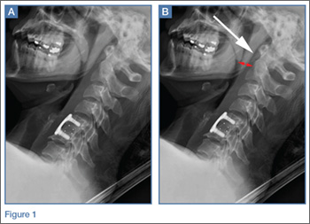
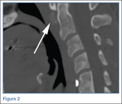
The lateral view of the cervical spine demonstrated soft tissue swelling in the upper prevertebral region (red arrowheads, Figure 1b). (The soft tissues at this level in an adult normally measure less than 3 mm between the airway and the vertebral body.) The radiograph also showed an area of calcification within the prevertebral soft tissues (white arrow, Figure 1b).
The patient denied fevers, chills, dysphagia, visual changes, and nasal congestion. Physical examination demonstrated tenderness to palpation of the posterior neck, but there was no evidence of palpable mass or lymphadenopathy. Neck extension and lateral movement to the left were severely limited due to pain; neck flexion and lateral movement range of motion to the right were mildly decreased due to pain. The physical examination was otherwise normal.
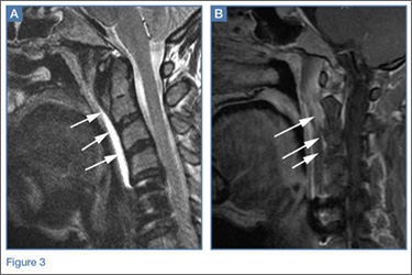
Longus colli (prevertebral) calcific tendinitis is a self-limiting condition that typically lasts 1 to 3 weeks, though it can be very painful during the acute phase.1,2 Treatment is typically conservative, and the patient in this case received a course of oral corticosteroids and nonsteroidal anti-inflammatory drugs to help alleviate the associated inflammation.
Dr Bartolotta is an assistant professor of radiology at Weill Cornell Medical College in New York City and assistant attending radiologist at New York-Presbyterian Hospital/Weill Cornell Medical Center. Dr Baradaran is a resident in the department of radiology at Weill Cornell Medical College in New York City. Dr Hentel is an associate professor of clinical radiology at Weill Cornell Medical College, New York. He is also chief of emergency/musculoskeletal imaging and executive vice-chairman for the department of radiology at New York-Presbyterian Hospital/Weill Cornell Medical Center; and associate editor, imaging, of the EMERGENCY MEDICINE editorial board.
- Coulier B, Macsim M, Desgain O. Retropharyngeal calcific tendinitis--longus colli tendinitis--an unusual cause of acute dysphagia. Emerg Radiol. 2011;18(5):449-451.
- Silva CF, Soffia PS, Pruzzo E. Acute prevertebral calcific tendinitis: a source of non-surgical acute cervical pain. Acta Radiologica. 2014;55(1):91-94.
- Zibis AH, Giannis D, Malizos KN, Kitsioulis P, Arvanitis DL. Acute calcific tendinitis of the longus colli muscle: case report and review of the literature. Eur Spine J. 2013;22(Suppl 3):S434-S438.
Case
A 41-year-old woman presented to the ED with a 3-day history of posterior neck pain that radiated to the occipital region. The patient stated that the day prior to presentation, the pain had worsened to what she rated as a “9” on a pain scale of 0 to 10. The patient’s surgical history included a remote prior cervical fusion at C5-C6. A lateral radiograph of the cervical spine is shown above (Figure 1a).
What is the diagnosis? Is additional imaging necessary? If so, why?
Answer
The lateral view of the cervical spine demonstrated soft tissue swelling in the upper prevertebral region (red arrowheads, Figure 1b). (The soft tissues at this level in an adult normally measure less than 3 mm between the airway and the vertebral body.) The radiograph also showed an area of calcification within the prevertebral soft tissues (white arrow, Figure 1b).
The patient denied fevers, chills, dysphagia, visual changes, and nasal congestion. Physical examination demonstrated tenderness to palpation of the posterior neck, but there was no evidence of palpable mass or lymphadenopathy. Neck extension and lateral movement to the left were severely limited due to pain; neck flexion and lateral movement range of motion to the right were mildly decreased due to pain. The physical examination was otherwise normal.
Longus colli (prevertebral) calcific tendinitis is a self-limiting condition that typically lasts 1 to 3 weeks, though it can be very painful during the acute phase.1,2 Treatment is typically conservative, and the patient in this case received a course of oral corticosteroids and nonsteroidal anti-inflammatory drugs to help alleviate the associated inflammation.
Dr Bartolotta is an assistant professor of radiology at Weill Cornell Medical College in New York City and assistant attending radiologist at New York-Presbyterian Hospital/Weill Cornell Medical Center. Dr Baradaran is a resident in the department of radiology at Weill Cornell Medical College in New York City. Dr Hentel is an associate professor of clinical radiology at Weill Cornell Medical College, New York. He is also chief of emergency/musculoskeletal imaging and executive vice-chairman for the department of radiology at New York-Presbyterian Hospital/Weill Cornell Medical Center; and associate editor, imaging, of the EMERGENCY MEDICINE editorial board.
- Coulier B, Macsim M, Desgain O. Retropharyngeal calcific tendinitis--longus colli tendinitis--an unusual cause of acute dysphagia. Emerg Radiol. 2011;18(5):449-451.
- Silva CF, Soffia PS, Pruzzo E. Acute prevertebral calcific tendinitis: a source of non-surgical acute cervical pain. Acta Radiologica. 2014;55(1):91-94.
- Zibis AH, Giannis D, Malizos KN, Kitsioulis P, Arvanitis DL. Acute calcific tendinitis of the longus colli muscle: case report and review of the literature. Eur Spine J. 2013;22(Suppl 3):S434-S438.
Percutaneous Fixation of Hypertrophic Nonunion of the Inferior Pubic Ramus: A Report of Two Cases and Surgical Technique
Fractures of the superior and inferior pelvic rami are common in pelvic ring injuries.1 These fractures are routinely treated successfully without surgery.2 When the pelvic ring is injured, and ramus fracture or fractures represent a point of instability, surgical fixation can be performed to impart stability and reduce discomfort.3 Patients with pubic ramus fracture(s) have overall greater long-term morbidity and mortality.4 Operative stabilization of the superior pubic ramus can be achieved with open reduction and internal fixation, external fixation, and percutaneous medullary screw fixation.5-8 Inferior ramus fractures are seldom treated directly and acutely with operative reduction and fixation, as the mechanical advantage inferior ramus fixation provides is unknown.
Persistent nonunion of the pelvic ring can cause pain and disability and make reconstruction increasingly difficult.9 Open and percutaneous fixation techniques have been used to address symptomatic nonunions of the superior pubic ramus.9,10 There is limited evidence supporting surgical fixation of the inferior ramus. Open surgical fixation for symptomatic nonunions of the inferior ramus has been described.11,12 The inferior ramus has an osseous fixation pathway (OFP) amenable to percutaneous screw placement.13 Placement of a percutaneous screw in the inferior ramus requires use of preoperative computed tomography (CT) and is technically demanding. Surgeons must understand use of intraoperative fluoroscopy to ensure that the screw is contained within bone and crosses the intended zone of nonunion.
In this article, we report 2 cases of adults with symptomatic hypertrophic nonunions of the inferior ramus, treated with percutaneous screw fixation. Both patients presented with focal groin pain and activity limitations. Each had concurrent ipsilateral hypertrophic nonunions of the superior ramus, treated with percutaneous antegrade intramedullary stabilization. The patients provided written informed consent for print and electronic publication of these case reports.
Case Reports
Case 1
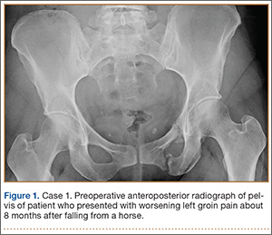
A 45-year-old woman fell from a horse about 8 months before presenting to the orthopedic outpatient clinic. Pelvic radiographs obtained after the fall were negative for fracture, but subsequent pelvic magnetic resonance imaging led to the diagnoses of minimally displaced left superior and inferior pubic ramus fractures and associated right-sided sacral ala fracture. The patient was treated with protected weight-bearing according to symptoms, but increasing activity-related pain and discomfort in the left groin persisted for months after injury. These symptoms were treated with analgesic medication, physical therapy, and chiropractic manipulation. Repeat imaging showed hypertrophic nonunions of the left superior and inferior pubic rami (Figure 1). Findings of the serologic testing performed for infection and metabolic deficiencies were normal at that time. The patient was referred for surgical consultation.
On evaluation, she reported constant pain in the left groin with ambulation. Specifically, squatting, pushing and pulling activities were extremely uncomfortable. She had been unable to return to work either full-time or part-time. On physical examination, she walked with an antalgic gait with a decreased stance phase of the left lower extremity. She had tenderness to palpation medial to the hip joint without evidence of hernia or lymphadenopathy. The pelvis was stable to manual compression testing.
Pelvic CT showed the nonunion site and the osteology of the inferior and superior pubic ramus of the pelvis, as well as minimal displacement and good alignment of the rami.
The patient was placed supine on a flat radiolucent table (Mizuho OSI, Union City, California). Preoperative cephalosporin antibiotics were administered. After induction of general anesthesia, the lumbosacral spine was elevated under 2 folded blankets. Arms were abducted to allow for pelvic imaging, and all bony prominences were padded. A urinary catheter was inserted aseptically to decompress the bladder. The entire abdomen and bilateral flanks were shaved, prepared, and draped in usual sterile fashion. A partially threaded cannulated screw was placed using a percutaneous antegrade technique to address the hypertrophic superior ramus nonunion.
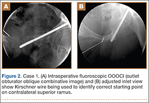
A C-arm fluoroscopy unit (Ziehm, Orlando, Florida) was positioned on the injured side. The surgeon stood on the contralateral side. A pelvic OOOCI (outlet obturator oblique combinative image) of the symphysis pubis was obtained. This view defined the medial and lateral extents of the inferior ramus. A 0.062-in smooth Kirschner wire was used to percutaneously locate an ideal starting point on the cranial aspect of the contralateral superior pubic ramus. The starting point was adjusted on this view until an ideal intended trajectory into the contralateral (affected) inferior pubic ramus was visualized (Figure 2A).
The C-arm beam was then oriented to an “excessive” pelvic inlet view tangential to the posterior cortical surface of the affected inferior pubic ramus (Figure 2B). The tip of the wire was then adjusted to position and aim it slightly anterior to the posterior cortical surface of the affected inferior ramus. The wire was advanced into the bone about 1 cm, and the location and direction of the wire were reconfirmed as accurate.
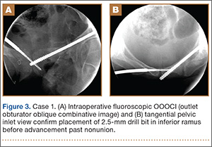
A vertical skin incision was then made around the wire, and the 4.5-mm cannulated drill was placed over the wire. A soft-tissue protective drill sleeve and oscillating technique were used to protect the soft-tissue anatomy. The trajectory of the drill was again confirmed on pelvic OOOCI and advanced into the bone. The intended path of the drill was from the cranial-medial symphyseal cortex of the contralateral superior ramus, through the symphysis pubis obliquely, and then into the medullary canal of the affected inferior ramus. Frequent biplanar fluoroscopic imaging followed this progression of the drill to the nonunion site. The cannulated drill was then removed and exchanged for a calibrated extra-long 2.5-mm drill bit, placed through the soft-tissue drill sleeve and into the glide hole created by the 4.5-mm cannulated drill. The C-arm unit ensured accurate positioning of the 2.5-mm drill on both pelvic OOOCI and “excessive” inlet view before advancement (Figures 3A, 3B). The 2.5-mm drill was advanced caudally, laterally, and anteriorly in the ramus, past the nonunion site, and then was stopped before it exited the cortex of the ischial tuberosity (Figures 4A, 4B).
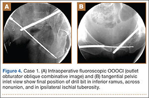
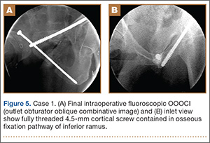
The depth of the drill bit was assessed with a known-length protective drill sleeve and calibrated drill. Alternatively, depth can be assessed with another same-length calibrated drill bit positioned adjacent to the inserted drill bit. A fully threaded, blunt-tipped 4.5-mm cortical screw was then placed through the glide hole. Both fluoroscopic views were used to confirm that the screw followed the same trajectory as the drill. Finally, the screw was again checked on biplanar fluoroscopy to confirm it had remained in the OFP of the inferior ramus (Figures 5A, 5B).
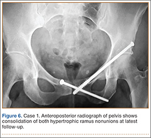
Postoperative pelvic CT confirmed position and length of the screws. The patient was allowed weight-of-limb weight-bearing on her affected side after surgery. She was discharged the first day after surgery and allowed use of oral analgesics. Six weeks after surgery, pelvic radiographs showed partial healing, and she reported symptom relief. Resistive strengthening exercises were instituted, and progressive weight-bearing proceeded to full weight-bearing over the next 6 weeks. The patient reported almost complete relief of pain by 3 months, and she was able to return to work and daily activities without medication. Radiographs showed consolidation of the fractures. She was essentially symptom-free 17 months after surgery (Figure 6).
Case 2
An obese 51-year-old woman presented to the orthopedic clinic with a 6-month history of left groin pain that worsened with ambulation. She did not recall a specific injury but acknowledged a history of previous falls. Past medical history was significant for ulcerative colitis/irritable bowel syndrome and degenerative disease in the lumbar spine and right ankle. Previous pelvic radiographs showed no evidence of fracture or abnormality, but radiographs obtained before evaluation in the clinic showed hypertrophic nonunion of the left superior and inferior pubic ramus.
The patient had pain deep in the left groin with weight-bearing. On physical examination, she denied pain with log roll of the left hip or resisted straight leg raise. The pelvis was stable to manual compression. There was no sign of hernia or lymphadenopathy in the region of the left groin.
The patient had obtained a technetium-99 nuclear medicine scan of the pelvis in addition to standard preoperative CT of the nonunion area. The nuclear medicine scan showed uptake in the area of the superior and inferior ramus, and CT confirmed presence of a superior and inferior ramus that would accommodate a medullary screw.
The patient was taken to the operating room, where percutaneous fixation of the left superior and inferior ramus was performed (as described above). The patient was discharged on postoperative day 2 and followed the same weight-bearing protocol that the first patient used.
At 6 weeks, the patient returned to clinic with improved comfort. At 3 months, she denied left groin pain and was limited in activity only by preexisting arthrosis in the left ankle and lumbar spine. She was using a walker only for long distances and was symptom-free 13 months after surgery.
Discussion
Acute surgical fixation of the inferior ramus is seldom performed. The anatomical location of the inferior ramus and the lack of defined criteria for fixation often leave the inferior ramus ignored, unreduced, and without stabilization. In the setting of symptomatic nonunion, open stabilization has been used.11,12 Plate fixation after open débridement of an inferior ramus nonunion requires more extensive dissection and may increase the risk for perioperative infection and hardware prominence compared with an intramedullary implant.14 If plate prominence becomes symptomatic, the plate must be removed in a second surgical procedure. Percutaneous medullary screw fixation avoids the risks of surgical soft-tissue dissection and placement of a surface implant on the bone and reduces the need for a second surgical procedure to remove bothersome hardware. Percutaneous pelvic fixation has been well described and shown to provide stability to the pelvis. It can also be used to treat hypertrophic nonunions of the pelvis when mechanical stability is required for healing.13
In the cases reported here, inferior ramus stabilization was combined with intramedullary fixation of the superior ramus. As each patient had deep groin pain that could not be localized to either ramus, both rami were stabilized after close assessment on preoperative CT. Solitary fixation of the superior ramus may or may not provide stability sufficient for inferior ramus union and should be performed when the OFP of the inferior ramus is unavailable.
The anatomy of the inferior ramus must be carefully reviewed before surgery, as it is seldom encountered in open and percutaneous orthopedic pelvic surgery. The inferior ramus extends from the symphysis pubis to the ischial tuberosity. The ramus is wider medially and thinner laterally near the obturator foramen. The anterior surface of the ramus is flat and concave, whereas the posterior surface is flat and convex. The anatomy of the inferior ramus varies somewhat, and any distortion (eg, fracture, nonunion) of the OFP can render it incapable of accommodating screw fixation.13
Percutaneous placement of a medullary screw in the inferior ramus requires an understanding of the fluoroscopy required. Challenges, including body habitus and unique osseous anatomy, must be recognized. Soft tissues must be protected with a drill sleeve during preparation of the screw pathway, and care must be taken to avoid placing the screw beyond the cortex of the ischial tuberosity. A prominent screw tip can irritate the patient in the hamstrings or while sitting.
Intramedullary screw fixation of the inferior ramus is a technically demanding surgical procedure. Meticulous evaluation of preoperative radiographic studies must accompany strict attention to surgical detail. A misplaced or malpositioned drill bit or screw can injure surrounding neurovascular structures. A screw that does not cross the fracture or is not in the OFP of the inferior ramus will be ineffective and
potentially dangerous.
Conclusion
We have presented a technique for percutaneous screw placement in the inferior ramus. This technique requires an understanding of the anatomy of the inferior ramus and of the intraoperative fluoroscopy required for screw placement. We have used this technique to successfully treat symptomatic hypertrophic nonunions of the inferior ramus that require skeletal stability for healing.
1. Hill RM, Robinson CM, Keating JF. Fractures of the pubic rami. Epidemiology and five-year survival. J Bone Joint Surg Br. 2001;83(8):1141-1144.
2. Matta JM, Dickson KF, Markovich GD. Surgical treatment of pelvic nonunions and malunions. Clin Orthop. 1996;(329):199-206.
3. Barei DP, Shafer BL, Beingessner DM, Gardner MJ, Nork SE, Routt ML. The impact of open reduction internal fixation on acute pain management in unstable pelvic ring injuries. J Trauma. 2010;68(4):949-953.
4. van Dijk WA, Poeze M, van Helden SH, Brink PR, Verbruggen JP. Ten-year mortality among hospitalised patients with fractures of the pubic rami. Injury. 2010;41(4):411-414.
5. Simonian PT, Routt ML Jr, Harrington RM, Tencer AF. Internal fixation of the unstable anterior pelvic ring: a biomechanical comparison of standard plating techniques and the retrograde medullary superior pubic ramus screw. J Orthop Trauma. 1994;8(6):476-482.
6. Routt ML Jr, Simonian PT, Grujic L. The retrograde medullary superior pubic ramus screw for the treatment of anterior pelvic ring disruptions: a new technique. J Orthop Trauma. 1995;9(1):35-44.
7. Matta JM. Indications for anterior fixation of pelvic fractures. Clin Orthop. 1996;(329):88-96.
8. Routt ML Jr, Nork SE, Mills WJ. Percutaneous fixation of pelvic ring disruptions. Clin Orthop. 2000;(375):15-29.
9. Gautier E, Rommens PM, Matta JM. Late reconstruction after pelvic ring injuries. Injury. 1996;27(suppl 2):B39-B46.
10. Altman GT, Altman DT, Routt ML Jr. Symptomatic hypertrophic pubic ramus nonunion treated with a retrograde medullary screw. J Orthop Trauma. 2000;14(8):582-585.
11. Archdeacon MT, Kuhlman G, Kazemi N. Fellow’s Corner: grand rounds from the University of Cincinnati Medical Center—painful superior and inferior pubic rami nonunion. J Orthop Trauma. 2010;24(11):e109-e112.
12. Schofer M, Illian C, Fuchs-Winkelmann S, Kortmann HR. Pseudoarthrosis of anterior pelvic ring fracture [in German]. Unfallchirurg. 2008;111(4):264, 266-267.
13. Bishop JA, Routt ML Jr. Osseous fixation pathways in pelvic and acetabular fracture surgery: osteology, radiology, and clinical applications. J Trauma Acute Care Surg. 2012;72(6):1502-1509.
14. Schmidt AH, Swiontkowski MF. Pathophysiology of infections after internal fixation of fractures. J Am Acad Orthop Surg. 2000;8(5):285-291.
Fractures of the superior and inferior pelvic rami are common in pelvic ring injuries.1 These fractures are routinely treated successfully without surgery.2 When the pelvic ring is injured, and ramus fracture or fractures represent a point of instability, surgical fixation can be performed to impart stability and reduce discomfort.3 Patients with pubic ramus fracture(s) have overall greater long-term morbidity and mortality.4 Operative stabilization of the superior pubic ramus can be achieved with open reduction and internal fixation, external fixation, and percutaneous medullary screw fixation.5-8 Inferior ramus fractures are seldom treated directly and acutely with operative reduction and fixation, as the mechanical advantage inferior ramus fixation provides is unknown.
Persistent nonunion of the pelvic ring can cause pain and disability and make reconstruction increasingly difficult.9 Open and percutaneous fixation techniques have been used to address symptomatic nonunions of the superior pubic ramus.9,10 There is limited evidence supporting surgical fixation of the inferior ramus. Open surgical fixation for symptomatic nonunions of the inferior ramus has been described.11,12 The inferior ramus has an osseous fixation pathway (OFP) amenable to percutaneous screw placement.13 Placement of a percutaneous screw in the inferior ramus requires use of preoperative computed tomography (CT) and is technically demanding. Surgeons must understand use of intraoperative fluoroscopy to ensure that the screw is contained within bone and crosses the intended zone of nonunion.
In this article, we report 2 cases of adults with symptomatic hypertrophic nonunions of the inferior ramus, treated with percutaneous screw fixation. Both patients presented with focal groin pain and activity limitations. Each had concurrent ipsilateral hypertrophic nonunions of the superior ramus, treated with percutaneous antegrade intramedullary stabilization. The patients provided written informed consent for print and electronic publication of these case reports.
Case Reports
Case 1
A 45-year-old woman fell from a horse about 8 months before presenting to the orthopedic outpatient clinic. Pelvic radiographs obtained after the fall were negative for fracture, but subsequent pelvic magnetic resonance imaging led to the diagnoses of minimally displaced left superior and inferior pubic ramus fractures and associated right-sided sacral ala fracture. The patient was treated with protected weight-bearing according to symptoms, but increasing activity-related pain and discomfort in the left groin persisted for months after injury. These symptoms were treated with analgesic medication, physical therapy, and chiropractic manipulation. Repeat imaging showed hypertrophic nonunions of the left superior and inferior pubic rami (Figure 1). Findings of the serologic testing performed for infection and metabolic deficiencies were normal at that time. The patient was referred for surgical consultation.
On evaluation, she reported constant pain in the left groin with ambulation. Specifically, squatting, pushing and pulling activities were extremely uncomfortable. She had been unable to return to work either full-time or part-time. On physical examination, she walked with an antalgic gait with a decreased stance phase of the left lower extremity. She had tenderness to palpation medial to the hip joint without evidence of hernia or lymphadenopathy. The pelvis was stable to manual compression testing.
Pelvic CT showed the nonunion site and the osteology of the inferior and superior pubic ramus of the pelvis, as well as minimal displacement and good alignment of the rami.
The patient was placed supine on a flat radiolucent table (Mizuho OSI, Union City, California). Preoperative cephalosporin antibiotics were administered. After induction of general anesthesia, the lumbosacral spine was elevated under 2 folded blankets. Arms were abducted to allow for pelvic imaging, and all bony prominences were padded. A urinary catheter was inserted aseptically to decompress the bladder. The entire abdomen and bilateral flanks were shaved, prepared, and draped in usual sterile fashion. A partially threaded cannulated screw was placed using a percutaneous antegrade technique to address the hypertrophic superior ramus nonunion.
A C-arm fluoroscopy unit (Ziehm, Orlando, Florida) was positioned on the injured side. The surgeon stood on the contralateral side. A pelvic OOOCI (outlet obturator oblique combinative image) of the symphysis pubis was obtained. This view defined the medial and lateral extents of the inferior ramus. A 0.062-in smooth Kirschner wire was used to percutaneously locate an ideal starting point on the cranial aspect of the contralateral superior pubic ramus. The starting point was adjusted on this view until an ideal intended trajectory into the contralateral (affected) inferior pubic ramus was visualized (Figure 2A).
The C-arm beam was then oriented to an “excessive” pelvic inlet view tangential to the posterior cortical surface of the affected inferior pubic ramus (Figure 2B). The tip of the wire was then adjusted to position and aim it slightly anterior to the posterior cortical surface of the affected inferior ramus. The wire was advanced into the bone about 1 cm, and the location and direction of the wire were reconfirmed as accurate.
A vertical skin incision was then made around the wire, and the 4.5-mm cannulated drill was placed over the wire. A soft-tissue protective drill sleeve and oscillating technique were used to protect the soft-tissue anatomy. The trajectory of the drill was again confirmed on pelvic OOOCI and advanced into the bone. The intended path of the drill was from the cranial-medial symphyseal cortex of the contralateral superior ramus, through the symphysis pubis obliquely, and then into the medullary canal of the affected inferior ramus. Frequent biplanar fluoroscopic imaging followed this progression of the drill to the nonunion site. The cannulated drill was then removed and exchanged for a calibrated extra-long 2.5-mm drill bit, placed through the soft-tissue drill sleeve and into the glide hole created by the 4.5-mm cannulated drill. The C-arm unit ensured accurate positioning of the 2.5-mm drill on both pelvic OOOCI and “excessive” inlet view before advancement (Figures 3A, 3B). The 2.5-mm drill was advanced caudally, laterally, and anteriorly in the ramus, past the nonunion site, and then was stopped before it exited the cortex of the ischial tuberosity (Figures 4A, 4B).
The depth of the drill bit was assessed with a known-length protective drill sleeve and calibrated drill. Alternatively, depth can be assessed with another same-length calibrated drill bit positioned adjacent to the inserted drill bit. A fully threaded, blunt-tipped 4.5-mm cortical screw was then placed through the glide hole. Both fluoroscopic views were used to confirm that the screw followed the same trajectory as the drill. Finally, the screw was again checked on biplanar fluoroscopy to confirm it had remained in the OFP of the inferior ramus (Figures 5A, 5B).
Postoperative pelvic CT confirmed position and length of the screws. The patient was allowed weight-of-limb weight-bearing on her affected side after surgery. She was discharged the first day after surgery and allowed use of oral analgesics. Six weeks after surgery, pelvic radiographs showed partial healing, and she reported symptom relief. Resistive strengthening exercises were instituted, and progressive weight-bearing proceeded to full weight-bearing over the next 6 weeks. The patient reported almost complete relief of pain by 3 months, and she was able to return to work and daily activities without medication. Radiographs showed consolidation of the fractures. She was essentially symptom-free 17 months after surgery (Figure 6).
Case 2
An obese 51-year-old woman presented to the orthopedic clinic with a 6-month history of left groin pain that worsened with ambulation. She did not recall a specific injury but acknowledged a history of previous falls. Past medical history was significant for ulcerative colitis/irritable bowel syndrome and degenerative disease in the lumbar spine and right ankle. Previous pelvic radiographs showed no evidence of fracture or abnormality, but radiographs obtained before evaluation in the clinic showed hypertrophic nonunion of the left superior and inferior pubic ramus.
The patient had pain deep in the left groin with weight-bearing. On physical examination, she denied pain with log roll of the left hip or resisted straight leg raise. The pelvis was stable to manual compression. There was no sign of hernia or lymphadenopathy in the region of the left groin.
The patient had obtained a technetium-99 nuclear medicine scan of the pelvis in addition to standard preoperative CT of the nonunion area. The nuclear medicine scan showed uptake in the area of the superior and inferior ramus, and CT confirmed presence of a superior and inferior ramus that would accommodate a medullary screw.
The patient was taken to the operating room, where percutaneous fixation of the left superior and inferior ramus was performed (as described above). The patient was discharged on postoperative day 2 and followed the same weight-bearing protocol that the first patient used.
At 6 weeks, the patient returned to clinic with improved comfort. At 3 months, she denied left groin pain and was limited in activity only by preexisting arthrosis in the left ankle and lumbar spine. She was using a walker only for long distances and was symptom-free 13 months after surgery.
Discussion
Acute surgical fixation of the inferior ramus is seldom performed. The anatomical location of the inferior ramus and the lack of defined criteria for fixation often leave the inferior ramus ignored, unreduced, and without stabilization. In the setting of symptomatic nonunion, open stabilization has been used.11,12 Plate fixation after open débridement of an inferior ramus nonunion requires more extensive dissection and may increase the risk for perioperative infection and hardware prominence compared with an intramedullary implant.14 If plate prominence becomes symptomatic, the plate must be removed in a second surgical procedure. Percutaneous medullary screw fixation avoids the risks of surgical soft-tissue dissection and placement of a surface implant on the bone and reduces the need for a second surgical procedure to remove bothersome hardware. Percutaneous pelvic fixation has been well described and shown to provide stability to the pelvis. It can also be used to treat hypertrophic nonunions of the pelvis when mechanical stability is required for healing.13
In the cases reported here, inferior ramus stabilization was combined with intramedullary fixation of the superior ramus. As each patient had deep groin pain that could not be localized to either ramus, both rami were stabilized after close assessment on preoperative CT. Solitary fixation of the superior ramus may or may not provide stability sufficient for inferior ramus union and should be performed when the OFP of the inferior ramus is unavailable.
The anatomy of the inferior ramus must be carefully reviewed before surgery, as it is seldom encountered in open and percutaneous orthopedic pelvic surgery. The inferior ramus extends from the symphysis pubis to the ischial tuberosity. The ramus is wider medially and thinner laterally near the obturator foramen. The anterior surface of the ramus is flat and concave, whereas the posterior surface is flat and convex. The anatomy of the inferior ramus varies somewhat, and any distortion (eg, fracture, nonunion) of the OFP can render it incapable of accommodating screw fixation.13
Percutaneous placement of a medullary screw in the inferior ramus requires an understanding of the fluoroscopy required. Challenges, including body habitus and unique osseous anatomy, must be recognized. Soft tissues must be protected with a drill sleeve during preparation of the screw pathway, and care must be taken to avoid placing the screw beyond the cortex of the ischial tuberosity. A prominent screw tip can irritate the patient in the hamstrings or while sitting.
Intramedullary screw fixation of the inferior ramus is a technically demanding surgical procedure. Meticulous evaluation of preoperative radiographic studies must accompany strict attention to surgical detail. A misplaced or malpositioned drill bit or screw can injure surrounding neurovascular structures. A screw that does not cross the fracture or is not in the OFP of the inferior ramus will be ineffective and
potentially dangerous.
Conclusion
We have presented a technique for percutaneous screw placement in the inferior ramus. This technique requires an understanding of the anatomy of the inferior ramus and of the intraoperative fluoroscopy required for screw placement. We have used this technique to successfully treat symptomatic hypertrophic nonunions of the inferior ramus that require skeletal stability for healing.
1. Hill RM, Robinson CM, Keating JF. Fractures of the pubic rami. Epidemiology and five-year survival. J Bone Joint Surg Br. 2001;83(8):1141-1144.
2. Matta JM, Dickson KF, Markovich GD. Surgical treatment of pelvic nonunions and malunions. Clin Orthop. 1996;(329):199-206.
3. Barei DP, Shafer BL, Beingessner DM, Gardner MJ, Nork SE, Routt ML. The impact of open reduction internal fixation on acute pain management in unstable pelvic ring injuries. J Trauma. 2010;68(4):949-953.
4. van Dijk WA, Poeze M, van Helden SH, Brink PR, Verbruggen JP. Ten-year mortality among hospitalised patients with fractures of the pubic rami. Injury. 2010;41(4):411-414.
5. Simonian PT, Routt ML Jr, Harrington RM, Tencer AF. Internal fixation of the unstable anterior pelvic ring: a biomechanical comparison of standard plating techniques and the retrograde medullary superior pubic ramus screw. J Orthop Trauma. 1994;8(6):476-482.
6. Routt ML Jr, Simonian PT, Grujic L. The retrograde medullary superior pubic ramus screw for the treatment of anterior pelvic ring disruptions: a new technique. J Orthop Trauma. 1995;9(1):35-44.
7. Matta JM. Indications for anterior fixation of pelvic fractures. Clin Orthop. 1996;(329):88-96.
8. Routt ML Jr, Nork SE, Mills WJ. Percutaneous fixation of pelvic ring disruptions. Clin Orthop. 2000;(375):15-29.
9. Gautier E, Rommens PM, Matta JM. Late reconstruction after pelvic ring injuries. Injury. 1996;27(suppl 2):B39-B46.
10. Altman GT, Altman DT, Routt ML Jr. Symptomatic hypertrophic pubic ramus nonunion treated with a retrograde medullary screw. J Orthop Trauma. 2000;14(8):582-585.
11. Archdeacon MT, Kuhlman G, Kazemi N. Fellow’s Corner: grand rounds from the University of Cincinnati Medical Center—painful superior and inferior pubic rami nonunion. J Orthop Trauma. 2010;24(11):e109-e112.
12. Schofer M, Illian C, Fuchs-Winkelmann S, Kortmann HR. Pseudoarthrosis of anterior pelvic ring fracture [in German]. Unfallchirurg. 2008;111(4):264, 266-267.
13. Bishop JA, Routt ML Jr. Osseous fixation pathways in pelvic and acetabular fracture surgery: osteology, radiology, and clinical applications. J Trauma Acute Care Surg. 2012;72(6):1502-1509.
14. Schmidt AH, Swiontkowski MF. Pathophysiology of infections after internal fixation of fractures. J Am Acad Orthop Surg. 2000;8(5):285-291.
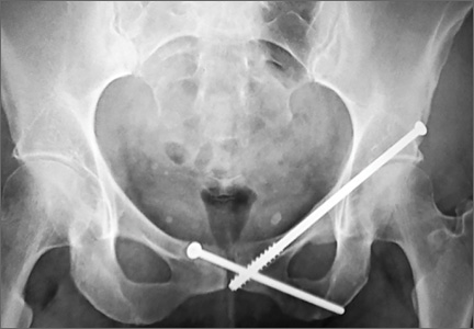
Retrograde Reamer/Irrigator/Aspirator Technique for Autologous Bone Graft Harvesting With the Patient in the Prone Position
The Reamer/Irrigator/Aspirator (RIA) system (Synthes, West Chester, Pennsylvania) has become a powerful tool for harvesting autologous bone graft from the intramedullary canal of the long bones of the lower extremity for the treatment of osseous defects, nonunions, and joint fusions.1,2 The RIA system provides satisfactory quality and quantity of bone graft (range, 40-90 mL)3-5 with osteogenic properties that rival those harvested from the iliac crest.6,7 Minimal donor-site morbidity and mortality have been reported in association with the RIA technique compared with iliac crest bone graft harvest.8
The RIA technique for the femur—with the antegrade approach and the supine position,8 with the antegrade approach and the prone position,9 and with the retrograde approach and the supine position4—has been described in the literature. To our knowledge, however, the RIA technique for the femur with the retrograde approach and the prone position has not been described. Antegrade harvesting uses the trochanteric entry point, and retrograde harvesting uses an entry at the intercondylar notch just anterior to the posterior cruciate ligament. In this article, we detail the technique for RIA harvesting of the femur with the patient in the prone position. Patient positioning is based on the diagnosis and the proposed procedure.
Advantages of a retrograde starting point include a more concentric trajectory (vs that of an antegrade starting point) and more efficient canal pressure reduction, which might decrease the risk of intraoperative fat embolization.10 This technique offers a more efficient solution to any procedure that requires the prone position, and it avoids the need to reposition, reprepare, or redrape the extremity. It is also very useful in treating obese patients.
After obtaining institutional review board (IRB) approval, we retrospectively reviewed patient files. Because the study was retrospective, the IRB waived the requirement for informed consent. The patients described here provided written informed consent for print and electronic publication of these case reports.
Surgical Technique
The patient is placed in a prone position on a radiolucent table with a bump under the thigh to allow access to the knee joint with full extension of the hip (Figures 1, 2A, 2B). The knee is then flexed to gain access to the intercondylar notch.
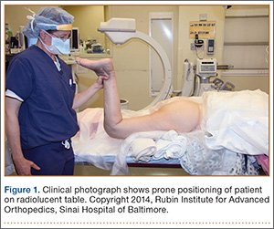
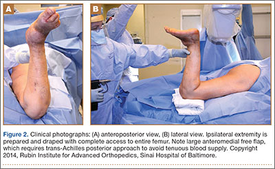
The anatomical axis of the femur is identified in the coronal and sagittal planes with the help of an image intensifier. Frequent intraoperative fluoroscopic imaging is required to prevent eccentric reaming and guide-wire movement from causing iatrogenic fractures and perforations, respectively.8 A 2-mm Steinmann pin is used to identify the point of entry into the femoral canal, which is located just above the posterior cruciate ligament insertion in the intercondylar notch, and care is taken not to ream this structure. A minimally invasive incision of about 15 mm is centered on this pin using a patellar tendon–splitting approach.
An 8-mm cannulated anterior cruciate ligament reamer is passed over the pin to enlarge the opening at the entry point, and a 2.5-mm ball-tipped guide wire is positioned in the femur. The image intensifier is used to confirm positioning of the guide in the trochanteric region and centered in the intramedullary canal. A radiolucent diving board facilitates fluoroscopic imaging.
The diameter (12.5 or 16.5 mm) of the reaming head is selected after the intramedullary guide is placed in the femoral canal. The isthmus of the femur is then identified radiographically, and a radiopaque ruler with increments in millimeters is used to measure the canal diameter (Figures 3A, 3B). Because the femoral canal is an ellipsoid, the canal diameter usually is much larger anteroposteriorly than laterally.8 We prefer to use a reaming head that overlaps the inner cortical diameter by 1 mm on each side. An alternative method includes measuring the outer diameter of the narrowest portion of the bone and using a reamer head no more than 45% of the outer diameter at the isthmus.8
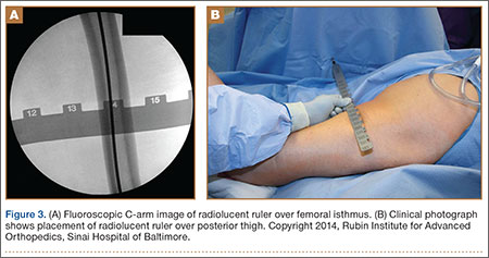
The RIA system is prepared on the back table by attaching the reaming head to the irrigation and suction systems. As the reamer head enters the intramedullary canal, an approach–withdraw–pause technique is used to slowly advance the reamer through the femur. It is crucial to use the image intensifier to guide reaming in order to avoid overdrilling the anterior cortex and prevent eccentric reaming of the canal, which more commonly occurs in patients with large anterior femoral bows.11 When the collection filter becomes full, reaming is stopped. The bone graft in the filter is emptied into a specimen cup for measurement and storage until subsequent use (Figure 4). Suctioning is suspended when reaming is stopped because substantial blood loss can occur with prolonged suction and aspiration.12 When repeat reaming is required, care is taken not to overream the cortices, thereby avoiding the risk of iatrogenic fracture.10,12
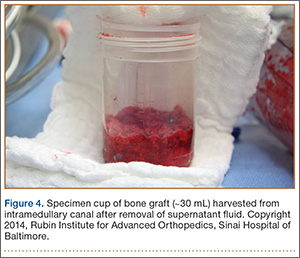
The knee joint is irrigated to remove any intramedullary debris. Typically there is no debris, as it is captured by the RIA. The wound is closed in 2 layers. Dressing with Ace bandage (3M, St. Paul, Minnesota) is placed around the knee for comfort. Weight-bearing status is determined by the index procedure.
Case Reports
Case 1
A 68-year-old female smoker presented to our facility with right ankle pain after recent ankle arthrodesis for pilon fracture nonunion. Almost 3 years earlier, the patient sustained a Gustilo-Anderson type II open pilon fracture in a motorcycle accident. She underwent antibiotic therapy, irrigation and débridement of the fracture site, and external fixation before definitive treatment with repeat irrigation and débridement and open reduction and internal fixation of the tibial plafond. About 6 months after surgery, she presented to her surgeon with a draining abscess over the anteromedial surgical incision. Multiple débridement procedures were performed, the implant was removed, the ankle was stabilized with a bridging external fixator, and culture-specific antibiotic therapy was administered. Intraoperative cultures confirmed methicillin-resistant Staphylococcus aureus. Vancomycin was administered intravenously for 6 weeks. Once C-reactive protein level and erythrocyte sedimentation rate returned to normal, repeat débridement with a rectus abdominis free flap and ankle fusion were performed.
When the patient presented to our clinic, we saw atrophic nonunion of the ankle fusion on radiographs. Smoking cessation was encouraged but not required before surgery. The patient returned to the operating suite for tibiotalocalcaneal fusion with a retrograde intramedullary nail. With the patient in the prone position, retrograde femoral RIA reaming was performed to harvest 30 mL of autologous bone. After resection of the nonunion site using a trans-Achilles approach and insertion of the intramedullary nail, the autologous bone graft was mixed with recombinant human bone morphogenetic protein 2 (BMP-2), and the mixture was introduced into the fusion site. At final follow-up, 18 months after surgery, the patient was clinically asymptomatic and radiographically healed—without further intervention and despite continued smoking. She did not report any knee pain from the harvest site.
Case 2
A 59-year-old noncompliant woman with diabetes and Charcot neuropathy sustained a trimalleolar ankle fracture-dislocation that was initially treated with ankle and hindfoot arthrodesis. The postoperative course was uneventful, and she was discharged home. Less than a week later, she presented to the emergency department with a midshaft tibial fracture just proximal to the ankle and hindfoot fusion nail. She subsequently had the device removed and a long arthrodesis rod inserted to span the fracture site up to the proximal tibial metadiaphysis. About 9 months later, she returned to our office complaining of ankle pain. No signs of infection were clinically evident. Radiographs showed nonunion of the ankle and subtalar joint. Findings of the initial bone biopsy and pathologic examination were negative for infection. The patient returned to the operating room 4 weeks later for revision ankle fusion. With the patient in the prone position, autologous bone (~30 mL) was harvested using retrograde femoral RIA reaming. The nonunion site was resected, and a mixture of autologous bone graft and BMP-2 was applied. Through a posterior approach, an anterior ankle arthrodesis locking plate was applied to the posterior aspect of the calcaneus and tibia. The patient was kept non-weight-bearing for 3 months and progressed in weight-bearing for another 4 to 6 weeks. Ambulatory status was restored about 4 months after surgery. No harvest-site knee pain was reported.
Discussion
Given its osteogenic, osteoconductive, and osteoinductive properties, autologous cancellous bone graft is the gold standard for reconstruction and fusion procedures in foot and ankle surgery.13 Bone graft can be obtained from many potential donor sites, but the most common is the iliac crest.2 However, many comorbidities, such as residual donor-site pain, neurovascular injuries, infection, and increased surgical time, have been reported in the literature.14,15 The RIA system was initially developed for simultaneous reaming and aspiration to reduce intramedullary pressure, heat generation, operating time, and the systemic effects of reaming, such as the embolic phenomenon.16-22 The single-pass reamer has provided a minimally invasive strategy for procuring voluminous amounts of autologous cancellous bone from the intramedullary canal of lower extremity long bones. Schmidmaier and colleagues3 recently quantified the measurements of several growth factors, such as insulinlike growth factor 1, transforming growth factor β 1, and BMP-2—proving that RIA-derived aspirates have amounts comparable to if not larger than those of iliac crest autologous bone graft. Pratt and colleagues23 provided insight into the possibility of induction of mesenchymal stem cells using the previously unwanted supernatant reamings after filtration. Recently, the RIA technique of autologous tibial and hindfoot bone graft harvest was described for use in ankle or tibiotalocalcaneal arthrodesis.2 Although this technique is a useful surgical option, tibia size remains a limiting factor. Kovar and Wozasek24 reported harvesting significantly more bone graft in the femur than in the tibia. A tibia that cannot accommodate the 12-mm (smallest) reamer head in the RIA system would be a contraindication. In addition, concerns about the association between tibial stress fractures and reaming of the entire tibial canal and concerns about the overall donor-site morbidity of the tibial shaft remain.
Conclusion
With its retrograde approach and prone positioning, this RIA technique is an effective and efficient solution for harvesting autologous femoral bone graft. Although we have described its use in ankle and hindfoot arthrodesis, this technique can be applied to any prone-position surgical procedure, including spine surgery.
1. Kobbe P, Tarkin IS, Frink M, Pape HC. Voluminous bone graft harvesting of the femoral marrow cavity for autologous transplantation. An indication for the “reamer-irrigator-aspirator-” (RIA-)technique [in German]. Unfallchirurg. 2008;111(6):469-472.
2. Herscovici D Jr, Scaduto JM. Use of the reamer-irrigator-aspirator technique to obtain autograft for ankle and hindfoot arthrodesis. J Bone Joint Surg Br. 2012;94(1):75-79.
3. Schmidmaier G, Herrmann S, Green J, et al. Quantitative assessment of growth factors in reaming aspirate, iliac crest, and platelet preparation. Bone. 2006;39(5):1156-1163.
4. Qvick LM, Ritter CA, Mutty CE, Rohrbacher BJ, Buyea CM, Anders MJ. Donor site morbidity with reamer-irrigator-aspirator (RIA) use for autogenous bone graft harvesting in a single centre 204 case series. Injury. 2013;44(10):1263-1269.
5. Lehman AA, Irgit KS, Cush GJ. Harvest of autogenous bone graft using reamer-irrigator-aspirator in tibiotalocalcaneal arthrodesis: surgical technique and case series. Foot Ankle Int. 2012;33(12):1133-1138.
6. Wildemann B, Kadow-Romacker A, Haas NP, Schmidmaier G. Quantification of various growth factors in different demineralized bone matrix preparations. J Biomed Mater Res A. 2007;81(2):437-442.
7. Sagi HC, Young ML, Gerstenfeld L, Einhorn TA, Tornetta P. Qualitative and quantitative differences between bone graft obtained from the medullary canal (with a reamer/irrigator/aspirator) and the iliac crest of the same patient. J Bone Joint Surg Am. 2012;94(23):2128-2135.
8. Belthur MV, Conway JD, Jindal G, Ranade A, Herzenberg JE. Bone graft harvest using a new intramedullary system. Clin Orthop. 2008;466(12):2973-2980.
9. Nichols TA, Sagi HC, Weber TG, Guiot BH. An alternative source of autograft bone for spinal fusion: the femur: technical case report. Neurosurgery. 2008;62(3 suppl 1):E179.
10. Van Gorp CC, Falk JV, Kmiec SJ Jr, Siston RA. The reamer/irrigator/aspirator reduces femoral canal pressure in simulated TKA. Clin Orthop. 2009;467(3):805-809.
11. Quintero AJ, Tarkin IS, Pape HC. Technical tricks when using the reamer irrigator aspirator technique for autologous bone graft harvesting. J Orthop Trauma. 2010;24(1):42-45.
12. Stafford PR, Norris B. Reamer-irrigator-aspirator as a bone graft harvester. Tech Foot Ankle Surg. 2007;6(2):100-107.
13. Whitehouse MR, Lankester BJ, Winson IG, Hepple S. Bone graft harvest from the proximal tibia in foot and ankle arthrodesis surgery. Foot Ankle Int. 2006;27(11):913-916.
14. Scharfenberger A, Weber T. RIA for bone graft harvest: applications for grafting large segmental defects in the tibia and femur. Presented at: 21st Annual Meeting of the Orthopaedic Trauma Association; 2005; Ottawa, Canada.
15. Arrington ED, Smith WJ, Chambers HG, Bucknell AL, Davino NA. Complications of iliac crest bone graft harvesting. Clin Orthop. 1996;(329):300-309.
16. Bedi A, Karunakar MA. Physiologic effects of intramedullary reaming. Instr Course Lect. 2006;55:359-366.
17. Higgins TF, Casey V, Bachus K. Cortical heat generation using an irrigating/aspirating single-pass reaming vs conventional stepwise reaming. J Orthop Trauma. 2007;21(3):192-197.
18. Husebye EE, Lyberg T, Madsen JE, Eriksen M, Røise O. The influence of a one-step reamer-irrigator-aspirator technique on the intramedullary pressure in the pig femur. Injury. 2006;37(10):935-940.
19. Müller CA, Green J, Südkamp NP. Physical and technical aspects of intramedullary reaming. Injury. 2006;37(suppl 4):S39-S49.
20. Pape HC, Dwenger A, Grotz M, et al. Does the reamer type influence the degree of lung dysfunction after femoral nailing following severe trauma? An animal study. J Orthop Trauma. 1994;8(4):300-309.
21. Pape HC, Zelle BA, Hildebrand F, Giannoudis PV, Krettek C, van Griensven M. Reamed femoral nailing in sheep: does irrigation and aspiration of intramedullary contents alter the systemic response? J Bone Joint Surg Am. 2005;87(11):2515-2522.
22. Schult M, Küchle R, Hofmann A, et al. Pathophysiological advantages of rinsing-suction-reaming (RSR) in a pig model for intramedullary nailing. J Orthop Res. 2006;24(6):1186-1192.
23. Pratt DJ, Papagiannopoulos G, Rees PH, Quinnell R. The effects of medullary reaming on the torsional strength of the femur. Injury. 1987;18(3):177-179.
24. Kovar FM, Wozasek GE. Bone graft harvesting using the RIA (reamer irrigation aspirator) system—a quantitative assessment. Wien Klin Wochenschr. 2011;123(9-10):285-290.
The Reamer/Irrigator/Aspirator (RIA) system (Synthes, West Chester, Pennsylvania) has become a powerful tool for harvesting autologous bone graft from the intramedullary canal of the long bones of the lower extremity for the treatment of osseous defects, nonunions, and joint fusions.1,2 The RIA system provides satisfactory quality and quantity of bone graft (range, 40-90 mL)3-5 with osteogenic properties that rival those harvested from the iliac crest.6,7 Minimal donor-site morbidity and mortality have been reported in association with the RIA technique compared with iliac crest bone graft harvest.8
The RIA technique for the femur—with the antegrade approach and the supine position,8 with the antegrade approach and the prone position,9 and with the retrograde approach and the supine position4—has been described in the literature. To our knowledge, however, the RIA technique for the femur with the retrograde approach and the prone position has not been described. Antegrade harvesting uses the trochanteric entry point, and retrograde harvesting uses an entry at the intercondylar notch just anterior to the posterior cruciate ligament. In this article, we detail the technique for RIA harvesting of the femur with the patient in the prone position. Patient positioning is based on the diagnosis and the proposed procedure.
Advantages of a retrograde starting point include a more concentric trajectory (vs that of an antegrade starting point) and more efficient canal pressure reduction, which might decrease the risk of intraoperative fat embolization.10 This technique offers a more efficient solution to any procedure that requires the prone position, and it avoids the need to reposition, reprepare, or redrape the extremity. It is also very useful in treating obese patients.
After obtaining institutional review board (IRB) approval, we retrospectively reviewed patient files. Because the study was retrospective, the IRB waived the requirement for informed consent. The patients described here provided written informed consent for print and electronic publication of these case reports.
Surgical Technique
The patient is placed in a prone position on a radiolucent table with a bump under the thigh to allow access to the knee joint with full extension of the hip (Figures 1, 2A, 2B). The knee is then flexed to gain access to the intercondylar notch.
The anatomical axis of the femur is identified in the coronal and sagittal planes with the help of an image intensifier. Frequent intraoperative fluoroscopic imaging is required to prevent eccentric reaming and guide-wire movement from causing iatrogenic fractures and perforations, respectively.8 A 2-mm Steinmann pin is used to identify the point of entry into the femoral canal, which is located just above the posterior cruciate ligament insertion in the intercondylar notch, and care is taken not to ream this structure. A minimally invasive incision of about 15 mm is centered on this pin using a patellar tendon–splitting approach.
An 8-mm cannulated anterior cruciate ligament reamer is passed over the pin to enlarge the opening at the entry point, and a 2.5-mm ball-tipped guide wire is positioned in the femur. The image intensifier is used to confirm positioning of the guide in the trochanteric region and centered in the intramedullary canal. A radiolucent diving board facilitates fluoroscopic imaging.
The diameter (12.5 or 16.5 mm) of the reaming head is selected after the intramedullary guide is placed in the femoral canal. The isthmus of the femur is then identified radiographically, and a radiopaque ruler with increments in millimeters is used to measure the canal diameter (Figures 3A, 3B). Because the femoral canal is an ellipsoid, the canal diameter usually is much larger anteroposteriorly than laterally.8 We prefer to use a reaming head that overlaps the inner cortical diameter by 1 mm on each side. An alternative method includes measuring the outer diameter of the narrowest portion of the bone and using a reamer head no more than 45% of the outer diameter at the isthmus.8
The RIA system is prepared on the back table by attaching the reaming head to the irrigation and suction systems. As the reamer head enters the intramedullary canal, an approach–withdraw–pause technique is used to slowly advance the reamer through the femur. It is crucial to use the image intensifier to guide reaming in order to avoid overdrilling the anterior cortex and prevent eccentric reaming of the canal, which more commonly occurs in patients with large anterior femoral bows.11 When the collection filter becomes full, reaming is stopped. The bone graft in the filter is emptied into a specimen cup for measurement and storage until subsequent use (Figure 4). Suctioning is suspended when reaming is stopped because substantial blood loss can occur with prolonged suction and aspiration.12 When repeat reaming is required, care is taken not to overream the cortices, thereby avoiding the risk of iatrogenic fracture.10,12
The knee joint is irrigated to remove any intramedullary debris. Typically there is no debris, as it is captured by the RIA. The wound is closed in 2 layers. Dressing with Ace bandage (3M, St. Paul, Minnesota) is placed around the knee for comfort. Weight-bearing status is determined by the index procedure.
Case Reports
Case 1
A 68-year-old female smoker presented to our facility with right ankle pain after recent ankle arthrodesis for pilon fracture nonunion. Almost 3 years earlier, the patient sustained a Gustilo-Anderson type II open pilon fracture in a motorcycle accident. She underwent antibiotic therapy, irrigation and débridement of the fracture site, and external fixation before definitive treatment with repeat irrigation and débridement and open reduction and internal fixation of the tibial plafond. About 6 months after surgery, she presented to her surgeon with a draining abscess over the anteromedial surgical incision. Multiple débridement procedures were performed, the implant was removed, the ankle was stabilized with a bridging external fixator, and culture-specific antibiotic therapy was administered. Intraoperative cultures confirmed methicillin-resistant Staphylococcus aureus. Vancomycin was administered intravenously for 6 weeks. Once C-reactive protein level and erythrocyte sedimentation rate returned to normal, repeat débridement with a rectus abdominis free flap and ankle fusion were performed.
When the patient presented to our clinic, we saw atrophic nonunion of the ankle fusion on radiographs. Smoking cessation was encouraged but not required before surgery. The patient returned to the operating suite for tibiotalocalcaneal fusion with a retrograde intramedullary nail. With the patient in the prone position, retrograde femoral RIA reaming was performed to harvest 30 mL of autologous bone. After resection of the nonunion site using a trans-Achilles approach and insertion of the intramedullary nail, the autologous bone graft was mixed with recombinant human bone morphogenetic protein 2 (BMP-2), and the mixture was introduced into the fusion site. At final follow-up, 18 months after surgery, the patient was clinically asymptomatic and radiographically healed—without further intervention and despite continued smoking. She did not report any knee pain from the harvest site.
Case 2
A 59-year-old noncompliant woman with diabetes and Charcot neuropathy sustained a trimalleolar ankle fracture-dislocation that was initially treated with ankle and hindfoot arthrodesis. The postoperative course was uneventful, and she was discharged home. Less than a week later, she presented to the emergency department with a midshaft tibial fracture just proximal to the ankle and hindfoot fusion nail. She subsequently had the device removed and a long arthrodesis rod inserted to span the fracture site up to the proximal tibial metadiaphysis. About 9 months later, she returned to our office complaining of ankle pain. No signs of infection were clinically evident. Radiographs showed nonunion of the ankle and subtalar joint. Findings of the initial bone biopsy and pathologic examination were negative for infection. The patient returned to the operating room 4 weeks later for revision ankle fusion. With the patient in the prone position, autologous bone (~30 mL) was harvested using retrograde femoral RIA reaming. The nonunion site was resected, and a mixture of autologous bone graft and BMP-2 was applied. Through a posterior approach, an anterior ankle arthrodesis locking plate was applied to the posterior aspect of the calcaneus and tibia. The patient was kept non-weight-bearing for 3 months and progressed in weight-bearing for another 4 to 6 weeks. Ambulatory status was restored about 4 months after surgery. No harvest-site knee pain was reported.
Discussion
Given its osteogenic, osteoconductive, and osteoinductive properties, autologous cancellous bone graft is the gold standard for reconstruction and fusion procedures in foot and ankle surgery.13 Bone graft can be obtained from many potential donor sites, but the most common is the iliac crest.2 However, many comorbidities, such as residual donor-site pain, neurovascular injuries, infection, and increased surgical time, have been reported in the literature.14,15 The RIA system was initially developed for simultaneous reaming and aspiration to reduce intramedullary pressure, heat generation, operating time, and the systemic effects of reaming, such as the embolic phenomenon.16-22 The single-pass reamer has provided a minimally invasive strategy for procuring voluminous amounts of autologous cancellous bone from the intramedullary canal of lower extremity long bones. Schmidmaier and colleagues3 recently quantified the measurements of several growth factors, such as insulinlike growth factor 1, transforming growth factor β 1, and BMP-2—proving that RIA-derived aspirates have amounts comparable to if not larger than those of iliac crest autologous bone graft. Pratt and colleagues23 provided insight into the possibility of induction of mesenchymal stem cells using the previously unwanted supernatant reamings after filtration. Recently, the RIA technique of autologous tibial and hindfoot bone graft harvest was described for use in ankle or tibiotalocalcaneal arthrodesis.2 Although this technique is a useful surgical option, tibia size remains a limiting factor. Kovar and Wozasek24 reported harvesting significantly more bone graft in the femur than in the tibia. A tibia that cannot accommodate the 12-mm (smallest) reamer head in the RIA system would be a contraindication. In addition, concerns about the association between tibial stress fractures and reaming of the entire tibial canal and concerns about the overall donor-site morbidity of the tibial shaft remain.
Conclusion
With its retrograde approach and prone positioning, this RIA technique is an effective and efficient solution for harvesting autologous femoral bone graft. Although we have described its use in ankle and hindfoot arthrodesis, this technique can be applied to any prone-position surgical procedure, including spine surgery.
1. Kobbe P, Tarkin IS, Frink M, Pape HC. Voluminous bone graft harvesting of the femoral marrow cavity for autologous transplantation. An indication for the “reamer-irrigator-aspirator-” (RIA-)technique [in German]. Unfallchirurg. 2008;111(6):469-472.
2. Herscovici D Jr, Scaduto JM. Use of the reamer-irrigator-aspirator technique to obtain autograft for ankle and hindfoot arthrodesis. J Bone Joint Surg Br. 2012;94(1):75-79.
3. Schmidmaier G, Herrmann S, Green J, et al. Quantitative assessment of growth factors in reaming aspirate, iliac crest, and platelet preparation. Bone. 2006;39(5):1156-1163.
4. Qvick LM, Ritter CA, Mutty CE, Rohrbacher BJ, Buyea CM, Anders MJ. Donor site morbidity with reamer-irrigator-aspirator (RIA) use for autogenous bone graft harvesting in a single centre 204 case series. Injury. 2013;44(10):1263-1269.
5. Lehman AA, Irgit KS, Cush GJ. Harvest of autogenous bone graft using reamer-irrigator-aspirator in tibiotalocalcaneal arthrodesis: surgical technique and case series. Foot Ankle Int. 2012;33(12):1133-1138.
6. Wildemann B, Kadow-Romacker A, Haas NP, Schmidmaier G. Quantification of various growth factors in different demineralized bone matrix preparations. J Biomed Mater Res A. 2007;81(2):437-442.
7. Sagi HC, Young ML, Gerstenfeld L, Einhorn TA, Tornetta P. Qualitative and quantitative differences between bone graft obtained from the medullary canal (with a reamer/irrigator/aspirator) and the iliac crest of the same patient. J Bone Joint Surg Am. 2012;94(23):2128-2135.
8. Belthur MV, Conway JD, Jindal G, Ranade A, Herzenberg JE. Bone graft harvest using a new intramedullary system. Clin Orthop. 2008;466(12):2973-2980.
9. Nichols TA, Sagi HC, Weber TG, Guiot BH. An alternative source of autograft bone for spinal fusion: the femur: technical case report. Neurosurgery. 2008;62(3 suppl 1):E179.
10. Van Gorp CC, Falk JV, Kmiec SJ Jr, Siston RA. The reamer/irrigator/aspirator reduces femoral canal pressure in simulated TKA. Clin Orthop. 2009;467(3):805-809.
11. Quintero AJ, Tarkin IS, Pape HC. Technical tricks when using the reamer irrigator aspirator technique for autologous bone graft harvesting. J Orthop Trauma. 2010;24(1):42-45.
12. Stafford PR, Norris B. Reamer-irrigator-aspirator as a bone graft harvester. Tech Foot Ankle Surg. 2007;6(2):100-107.
13. Whitehouse MR, Lankester BJ, Winson IG, Hepple S. Bone graft harvest from the proximal tibia in foot and ankle arthrodesis surgery. Foot Ankle Int. 2006;27(11):913-916.
14. Scharfenberger A, Weber T. RIA for bone graft harvest: applications for grafting large segmental defects in the tibia and femur. Presented at: 21st Annual Meeting of the Orthopaedic Trauma Association; 2005; Ottawa, Canada.
15. Arrington ED, Smith WJ, Chambers HG, Bucknell AL, Davino NA. Complications of iliac crest bone graft harvesting. Clin Orthop. 1996;(329):300-309.
16. Bedi A, Karunakar MA. Physiologic effects of intramedullary reaming. Instr Course Lect. 2006;55:359-366.
17. Higgins TF, Casey V, Bachus K. Cortical heat generation using an irrigating/aspirating single-pass reaming vs conventional stepwise reaming. J Orthop Trauma. 2007;21(3):192-197.
18. Husebye EE, Lyberg T, Madsen JE, Eriksen M, Røise O. The influence of a one-step reamer-irrigator-aspirator technique on the intramedullary pressure in the pig femur. Injury. 2006;37(10):935-940.
19. Müller CA, Green J, Südkamp NP. Physical and technical aspects of intramedullary reaming. Injury. 2006;37(suppl 4):S39-S49.
20. Pape HC, Dwenger A, Grotz M, et al. Does the reamer type influence the degree of lung dysfunction after femoral nailing following severe trauma? An animal study. J Orthop Trauma. 1994;8(4):300-309.
21. Pape HC, Zelle BA, Hildebrand F, Giannoudis PV, Krettek C, van Griensven M. Reamed femoral nailing in sheep: does irrigation and aspiration of intramedullary contents alter the systemic response? J Bone Joint Surg Am. 2005;87(11):2515-2522.
22. Schult M, Küchle R, Hofmann A, et al. Pathophysiological advantages of rinsing-suction-reaming (RSR) in a pig model for intramedullary nailing. J Orthop Res. 2006;24(6):1186-1192.
23. Pratt DJ, Papagiannopoulos G, Rees PH, Quinnell R. The effects of medullary reaming on the torsional strength of the femur. Injury. 1987;18(3):177-179.
24. Kovar FM, Wozasek GE. Bone graft harvesting using the RIA (reamer irrigation aspirator) system—a quantitative assessment. Wien Klin Wochenschr. 2011;123(9-10):285-290.
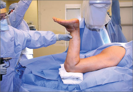
Costs a wash between CTA and functional chest pain testing
SAN DIEGO– After the first 90 days, there is very little difference in costs out to 3 years between CT angiography and functional testing in the initial evaluation of stable patients with new chest pain, an economic substudy of the PROMISE trial showed.
“CT coronary angiography may not be the ‘holy grail’ of diagnostic tests that we once envisioned, but its more liberal use based on the results of PROMISE may improve some aspects of patient care and I don’t think will be a major new economic burden on the health care system,” study author Dr. Daniel B. Mark said at the annual meeting of the American College of Cardiology.
The PROMISE trial, also presented at the ACA meeting, found no advantage with respect to hard clinical outcomes between the two initial testing strategies, but CTA led to fewer catheterizations showing no obstructive disease and a twofold increase in revascularizations.
The economic analysis involved initial test technical fees, hospital-based facility costs, and physician professional fees for testing and hospital services for 96% of the 9,649 patients in the study.
The estimated cost of CT angiography, including physician fees and technical fees, was $404, compared with $174 for exercise treadmill testing, $501 for echocardiography with pharmacologic stress, $514 for echo with exercise stress, $946 for nuclear testing with exercise stress, and $1,132 for nuclear testing with pharmacologic stress, said Dr. Mark, director of outcomes research at Duke Clinical Research Institute, Durham, N.C.
The trend toward higher costs with CT angiography was driven largely by more revascularizations, with very in little added costs occurring after 90 days, he noted.
An analysis that factored in what was done to patients after their initial test showed CT angiography was more expensive than functional testing by an average of $279 at 90 days, $358 at 1 year, $388 at 2 years, and $694 at 3 years. The 95% confidence intervals were wide, so none of the differences were statistically significant, he said.

A number of patients underwent very expensive noncardiovascular procedures in the third year that bumped the average cost up in the CT arm, “but we don’t think this has anything to do with the strategies to which they were randomized,” Dr. Mark explained.
Caveats to the analysis include use of an external data source (Premier Research Database) for initial diagnostic testing costs, outpatient medications were not counted, and significant deviations in testing costs by centers that might alter cost results of the two strategies. Quality of life and employment status are also still being analyzed, Dr. Mark said.
A cost-effectiveness analysis was not performed because CT angiography outcomes were not superior as hypothesized in PROMISE.
The study was funded by the National Institutes of Health. Dr. Mark disclosed consulting for Milestone, Medtronic, CardioDx, and St. Jude Medical and research grants from the NIH, Eli Lilly, AstraZeneca, Gilead, AGA Medical, and Bristol-Myers Squibb.
SAN DIEGO– After the first 90 days, there is very little difference in costs out to 3 years between CT angiography and functional testing in the initial evaluation of stable patients with new chest pain, an economic substudy of the PROMISE trial showed.
“CT coronary angiography may not be the ‘holy grail’ of diagnostic tests that we once envisioned, but its more liberal use based on the results of PROMISE may improve some aspects of patient care and I don’t think will be a major new economic burden on the health care system,” study author Dr. Daniel B. Mark said at the annual meeting of the American College of Cardiology.
The PROMISE trial, also presented at the ACA meeting, found no advantage with respect to hard clinical outcomes between the two initial testing strategies, but CTA led to fewer catheterizations showing no obstructive disease and a twofold increase in revascularizations.
The economic analysis involved initial test technical fees, hospital-based facility costs, and physician professional fees for testing and hospital services for 96% of the 9,649 patients in the study.
The estimated cost of CT angiography, including physician fees and technical fees, was $404, compared with $174 for exercise treadmill testing, $501 for echocardiography with pharmacologic stress, $514 for echo with exercise stress, $946 for nuclear testing with exercise stress, and $1,132 for nuclear testing with pharmacologic stress, said Dr. Mark, director of outcomes research at Duke Clinical Research Institute, Durham, N.C.
The trend toward higher costs with CT angiography was driven largely by more revascularizations, with very in little added costs occurring after 90 days, he noted.
An analysis that factored in what was done to patients after their initial test showed CT angiography was more expensive than functional testing by an average of $279 at 90 days, $358 at 1 year, $388 at 2 years, and $694 at 3 years. The 95% confidence intervals were wide, so none of the differences were statistically significant, he said.
A number of patients underwent very expensive noncardiovascular procedures in the third year that bumped the average cost up in the CT arm, “but we don’t think this has anything to do with the strategies to which they were randomized,” Dr. Mark explained.
Caveats to the analysis include use of an external data source (Premier Research Database) for initial diagnostic testing costs, outpatient medications were not counted, and significant deviations in testing costs by centers that might alter cost results of the two strategies. Quality of life and employment status are also still being analyzed, Dr. Mark said.
A cost-effectiveness analysis was not performed because CT angiography outcomes were not superior as hypothesized in PROMISE.
The study was funded by the National Institutes of Health. Dr. Mark disclosed consulting for Milestone, Medtronic, CardioDx, and St. Jude Medical and research grants from the NIH, Eli Lilly, AstraZeneca, Gilead, AGA Medical, and Bristol-Myers Squibb.
AT ACC 2015

Emergency Ultrasound: Soft-Tissue Assessment
Background
Emergency physicians and other clinicians frequently encounter patients presenting with soft-tissue complaints. Oftentimes, there is diagnostic uncertainty as to whether a patient has cellulitis, an abscess, or both. A prospective observational study by Tayal et al,1 demonstrated that bedside ultrasound assisted in identifying and differentiating abscess versus cellulitis, altering management in half of the patients.
Anatomy
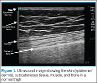
The epidermis and dermis are indistinguishable by ultrasound, and appear as a single thin bright layer. Below the epidermis and dermis, the subcutaneous layer appears as dark layer, which represents fat and bright connective tissue layer. Deep to that is the fascia, which is a linear bright layer. Below the fascia, muscle fascicles can be seen, which appear as bright striations in a fibrillar pattern.
Preparation and Technique

For practical and infection-control purposes, a tegaderm barrier dressing is recommended for covering the end of the probe (Figure 2). Structures should be viewed in at least two planes (ie, longitudinal and short axis).
Cellulitis

. This finding, however, is not specific to cellulitis alone, but can be seen in other conditions that cause interstitial swelling, such as congestive heart failure and peripheral edema.
Abscess
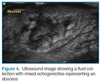
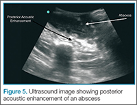
Putting a little downward pressure with the linear transducer over the abscess can produce swirling or movement within the abscess cavity, and has been informally coined “pustalsis” (Figure 5).
Lymph Nodes
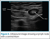
If color flow is placed on the area, blood flow into the node can be seen. Ultrasound can avoid unnecessary incision and drainage procedure in a patient with lymphadenopathy.
Conclusion
Bedside ultrasound is a useful and easily accessible tool to confirm the diagnosis and facilitate treatment in patients with soft-tissue complaints, including cellulitis, abscess, and lymphadenopathy. This modality is especially helpful in identifying vascular structures in areas such as the axilla or groin when incision and drainage are indicated, and can also help avoid mistaking an abdominal wall hernia for an abscess.
Dr Meer is an assistant professor and director of emergency ultrasound, department of emergency medicine, Emory University School of Medicine, Atlanta, Georgia. Dr Taylor is an assistant professor and director of postgraduate medical education, department of emergency medicine, Emory University School of Medicine, Atlanta, Georgia. Dr Beck is an assistant professor, department of emergency medicine, Emory University School of Medicine, Atlanta, Georgia.
Reference
- Tayal VS, Hasan N, Norton HJ, Tomaszewski CA. The effect of soft-tissue ultrasound on the management of cellulitis in the emergency department. Acad Emerg Med. 2006;13(4):384-388.
Background
Emergency physicians and other clinicians frequently encounter patients presenting with soft-tissue complaints. Oftentimes, there is diagnostic uncertainty as to whether a patient has cellulitis, an abscess, or both. A prospective observational study by Tayal et al,1 demonstrated that bedside ultrasound assisted in identifying and differentiating abscess versus cellulitis, altering management in half of the patients.
Anatomy
The epidermis and dermis are indistinguishable by ultrasound, and appear as a single thin bright layer. Below the epidermis and dermis, the subcutaneous layer appears as dark layer, which represents fat and bright connective tissue layer. Deep to that is the fascia, which is a linear bright layer. Below the fascia, muscle fascicles can be seen, which appear as bright striations in a fibrillar pattern.
Preparation and Technique
For practical and infection-control purposes, a tegaderm barrier dressing is recommended for covering the end of the probe (Figure 2). Structures should be viewed in at least two planes (ie, longitudinal and short axis).
Cellulitis
. This finding, however, is not specific to cellulitis alone, but can be seen in other conditions that cause interstitial swelling, such as congestive heart failure and peripheral edema.
Abscess
Putting a little downward pressure with the linear transducer over the abscess can produce swirling or movement within the abscess cavity, and has been informally coined “pustalsis” (Figure 5).
Lymph Nodes
If color flow is placed on the area, blood flow into the node can be seen. Ultrasound can avoid unnecessary incision and drainage procedure in a patient with lymphadenopathy.
Conclusion
Bedside ultrasound is a useful and easily accessible tool to confirm the diagnosis and facilitate treatment in patients with soft-tissue complaints, including cellulitis, abscess, and lymphadenopathy. This modality is especially helpful in identifying vascular structures in areas such as the axilla or groin when incision and drainage are indicated, and can also help avoid mistaking an abdominal wall hernia for an abscess.
Dr Meer is an assistant professor and director of emergency ultrasound, department of emergency medicine, Emory University School of Medicine, Atlanta, Georgia. Dr Taylor is an assistant professor and director of postgraduate medical education, department of emergency medicine, Emory University School of Medicine, Atlanta, Georgia. Dr Beck is an assistant professor, department of emergency medicine, Emory University School of Medicine, Atlanta, Georgia.
Reference
- Tayal VS, Hasan N, Norton HJ, Tomaszewski CA. The effect of soft-tissue ultrasound on the management of cellulitis in the emergency department. Acad Emerg Med. 2006;13(4):384-388.
Reference
- Tayal VS, Hasan N, Norton HJ, Tomaszewski CA. The effect of soft-tissue ultrasound on the management of cellulitis in the emergency department. Acad Emerg Med. 2006;13(4):384-388.

Heart on the right may sometimes be ‘right’
A 76-year-old man presented to the emergency department with right-sided exertional chest pain radiating to the right shoulder and arm associated with shortness of breath. His vital signs were normal. On clinical examination, the cardiac apex was palpated on the right side, 9 cm from the midsternal line in the fifth intercostal space.
A standard left-sided 12-lead electrocardiogram (ECG) showed right-axis deviation and inverted P, QRS, and T waves in leads I and aVL (Figure 1). Although these changes are also seen when the right and left arm electrode wires are transposed, the precordial lead morphology in such a situation would usually be normal. In our patient, the precordial leads showed the absence or even slight reversal of R-wave progression, a feature indicative of dextrocardia.1,2
In patients with dextrocardia, right-sided hookup of the electrodes is usually necessary for proper interpretation of the ECG. When this was done in our patient, the ECG showed a normal cardiac axis, a negative QRS complex in lead aVR, a positive P wave and other complexes in lead I, and normal R-wave progression in the precordial leads—findings suggestive of dextrocardia (Figure 2).
Chest radiography showed a right-sided cardiac silhouette (Figure 3), and computed tomography of the abdomen (Figure 4) revealed the liver positioned on the left side and the spleen on the right, confirming the diagnosis of situs inversus totalis. The ECG showed dextrocardia, but no other abnormalities. The patient eventually underwent coronary angiography, which showed nonobstructive coronary artery disease.
DEXTROCARDIA, OTHER CONGENITAL CARDIOVASCULAR MALFORMATIONS
Dextrocardia was first described in early 17th century.1 Situs solitus is the normal position of the heart and viscera, whereas situs inversus is a mirror-image anatomic arrangement of the organs. Situs inversus with dextrocardia, also called situs inversus totalis, is a rare condition (with a prevalence of 1 in 8,000) in which the heart and descending aorta are on the right and the thoracic and abdominal viscera are usually mirror images of the normal morphology.1,3,4 A mirror-image sinus node lies at the junction of the left superior vena cava and the left-sided (morphologic right) atrium.1 People with situs inversus with dextrocardia are usually asymptomatic and have a normal life expectancy.1,2 Situs inversus with levocardia is a rare condition in which the heart is in the normal position but the viscera are in the dextro-position. This anomaly has a prevalence of 1 in 22,000.5
Atrial situs almost always corresponds to visceral situs. However, when the alignment of the atria and viscera is inconsistent and situs cannot be determined clearly because of the malpositioning of organs, the condition is called “situs ambiguous.” This is very rare, with a prevalence of 1 in 40,000.6
Risk factors
The cause of congenital cardiovascular malformations such as these is not known, but risk factors include positive family history, maternal diabetes, and cocaine use in the first trimester.7
The prevalence of congenital heart disease in patients with situs inversus with dextrocardia is low and ranges from 2% to 5%. This is in contrast to situs solitus with dextrocardia (isolated dextrocardia), which is almost always associated with cardiovascular anomalies.2,4 Kartagener syndrome—the triad of situs inversus, sinusitis, and bronchiectasis—occurs in 25% of people with situs inversus with dextrocardia.4 Situs inversus with levocardia is also frequently associated with cardiac anomalies.5
The major features of dextrocardia on ECG are:
- Negative P wave, QRS complex, and T wave in lead I
- Positive QRS complex in aVR
- Right-axis deviation
- Reversal of R-wave progression in the precordial leads.
Ventricular activation and repolarization are reversed, resulting in a negative QRS complex and an inverted T wave in lead I. The absence of R-wave progression in the precordial leads helps differentiate mirror-image dextrocardia from erroneously reversed limb-electrode placement, which shows normal R-wave progression from V1 to V6 while showing similar features to those seen in dextrocardia in the limb leads.2 In right-sided hookup, the limb electrodes are reversed, and the chest electrodes are recorded from the right precordium.
CORONARY INTERVENTIONS REQUIRE SPECIAL CONSIDERATION
In patients with dextrocardia, coronary interventions can be challenging because of the mirror-image position of the coronary ostia and the aortic arch.8 These patients also need careful imaging, consideration of other associated congenital cardiac abnormalities, and detailed planning before cardiac surgery, including coronary artery bypass grafting.9
Patients with dextrocardia may present with cardiac symptoms localized to the right side of the body and have confusing clinical and diagnostic findings. Keeping dextrocardia and other such anomalies in mind can prevent delay in appropriately directed interventions. In a patient such as ours, the heart on the right side of the chest may indeed be “right.” Still, diagnostic tests to look for disorders encountered with dextrocardia may be necessary.
- Perloff JK. The cardiac malpositions. Am J Cardiol 2011; 108:1352–1361.
- Tanawuttiwat T, Vasaiwala S, Dia M. ECG image of the month. Mirror mirror. Am J Med 2010; 123:34–36.
- Douard R, Feldman A, Bargy F, Loric S, Delmas V. Anomalies of lateralization in man: a case of total situs in-versus. Surg Radiol Anat 2000; 22:293–297.
- Maldjian PD, Saric M. Approach to dextrocardia in adults: review. AJR Am J Roentgenol 2007; 188(suppl 6):S39–S49.
- Gindes L, Hegesh J, Barkai G, Jacobson JM, Achiron R. Isolated levocardia: prenatal diagnosis, clinical im-portance, and literature review. J Ultrasound Med 2007; 26:361–365.
- Abut E, Arman A, Güveli H, et al. Malposition of internal organs: a case of situs ambiguous anomaly in an adult. Turk J Gastroenterol 2003; 14:151–155.
- Kuehl KS, Loffredo C. Risk factors for heart disease associated with abnormal sidedness. Teratology 2002; 66:242–248.
- Aksoy S, Cam N, Gurkan U, Altay S, Bozbay M, Agirbasli M. Primary percutaneous intervention: for acute myo-cardial infarction in a patient with dextrocardia and situs inversus. Tex Heart Inst J 2012; 39:140–141.
- Murtuza B, Gupta P, Goli G, Lall KS. Coronary revascularization in adults with dextrocardia: surgical implications of the anatomic variants. Tex Heart Inst J 2010; 37:633–640.
A 76-year-old man presented to the emergency department with right-sided exertional chest pain radiating to the right shoulder and arm associated with shortness of breath. His vital signs were normal. On clinical examination, the cardiac apex was palpated on the right side, 9 cm from the midsternal line in the fifth intercostal space.
A standard left-sided 12-lead electrocardiogram (ECG) showed right-axis deviation and inverted P, QRS, and T waves in leads I and aVL (Figure 1). Although these changes are also seen when the right and left arm electrode wires are transposed, the precordial lead morphology in such a situation would usually be normal. In our patient, the precordial leads showed the absence or even slight reversal of R-wave progression, a feature indicative of dextrocardia.1,2
In patients with dextrocardia, right-sided hookup of the electrodes is usually necessary for proper interpretation of the ECG. When this was done in our patient, the ECG showed a normal cardiac axis, a negative QRS complex in lead aVR, a positive P wave and other complexes in lead I, and normal R-wave progression in the precordial leads—findings suggestive of dextrocardia (Figure 2).
Chest radiography showed a right-sided cardiac silhouette (Figure 3), and computed tomography of the abdomen (Figure 4) revealed the liver positioned on the left side and the spleen on the right, confirming the diagnosis of situs inversus totalis. The ECG showed dextrocardia, but no other abnormalities. The patient eventually underwent coronary angiography, which showed nonobstructive coronary artery disease.
DEXTROCARDIA, OTHER CONGENITAL CARDIOVASCULAR MALFORMATIONS
Dextrocardia was first described in early 17th century.1 Situs solitus is the normal position of the heart and viscera, whereas situs inversus is a mirror-image anatomic arrangement of the organs. Situs inversus with dextrocardia, also called situs inversus totalis, is a rare condition (with a prevalence of 1 in 8,000) in which the heart and descending aorta are on the right and the thoracic and abdominal viscera are usually mirror images of the normal morphology.1,3,4 A mirror-image sinus node lies at the junction of the left superior vena cava and the left-sided (morphologic right) atrium.1 People with situs inversus with dextrocardia are usually asymptomatic and have a normal life expectancy.1,2 Situs inversus with levocardia is a rare condition in which the heart is in the normal position but the viscera are in the dextro-position. This anomaly has a prevalence of 1 in 22,000.5
Atrial situs almost always corresponds to visceral situs. However, when the alignment of the atria and viscera is inconsistent and situs cannot be determined clearly because of the malpositioning of organs, the condition is called “situs ambiguous.” This is very rare, with a prevalence of 1 in 40,000.6
Risk factors
The cause of congenital cardiovascular malformations such as these is not known, but risk factors include positive family history, maternal diabetes, and cocaine use in the first trimester.7
The prevalence of congenital heart disease in patients with situs inversus with dextrocardia is low and ranges from 2% to 5%. This is in contrast to situs solitus with dextrocardia (isolated dextrocardia), which is almost always associated with cardiovascular anomalies.2,4 Kartagener syndrome—the triad of situs inversus, sinusitis, and bronchiectasis—occurs in 25% of people with situs inversus with dextrocardia.4 Situs inversus with levocardia is also frequently associated with cardiac anomalies.5
The major features of dextrocardia on ECG are:
- Negative P wave, QRS complex, and T wave in lead I
- Positive QRS complex in aVR
- Right-axis deviation
- Reversal of R-wave progression in the precordial leads.
Ventricular activation and repolarization are reversed, resulting in a negative QRS complex and an inverted T wave in lead I. The absence of R-wave progression in the precordial leads helps differentiate mirror-image dextrocardia from erroneously reversed limb-electrode placement, which shows normal R-wave progression from V1 to V6 while showing similar features to those seen in dextrocardia in the limb leads.2 In right-sided hookup, the limb electrodes are reversed, and the chest electrodes are recorded from the right precordium.
CORONARY INTERVENTIONS REQUIRE SPECIAL CONSIDERATION
In patients with dextrocardia, coronary interventions can be challenging because of the mirror-image position of the coronary ostia and the aortic arch.8 These patients also need careful imaging, consideration of other associated congenital cardiac abnormalities, and detailed planning before cardiac surgery, including coronary artery bypass grafting.9
Patients with dextrocardia may present with cardiac symptoms localized to the right side of the body and have confusing clinical and diagnostic findings. Keeping dextrocardia and other such anomalies in mind can prevent delay in appropriately directed interventions. In a patient such as ours, the heart on the right side of the chest may indeed be “right.” Still, diagnostic tests to look for disorders encountered with dextrocardia may be necessary.
- Perloff JK. The cardiac malpositions. Am J Cardiol 2011; 108:1352–1361.
- Tanawuttiwat T, Vasaiwala S, Dia M. ECG image of the month. Mirror mirror. Am J Med 2010; 123:34–36.
- Douard R, Feldman A, Bargy F, Loric S, Delmas V. Anomalies of lateralization in man: a case of total situs in-versus. Surg Radiol Anat 2000; 22:293–297.
- Maldjian PD, Saric M. Approach to dextrocardia in adults: review. AJR Am J Roentgenol 2007; 188(suppl 6):S39–S49.
- Gindes L, Hegesh J, Barkai G, Jacobson JM, Achiron R. Isolated levocardia: prenatal diagnosis, clinical im-portance, and literature review. J Ultrasound Med 2007; 26:361–365.
- Abut E, Arman A, Güveli H, et al. Malposition of internal organs: a case of situs ambiguous anomaly in an adult. Turk J Gastroenterol 2003; 14:151–155.
- Kuehl KS, Loffredo C. Risk factors for heart disease associated with abnormal sidedness. Teratology 2002; 66:242–248.
- Aksoy S, Cam N, Gurkan U, Altay S, Bozbay M, Agirbasli M. Primary percutaneous intervention: for acute myo-cardial infarction in a patient with dextrocardia and situs inversus. Tex Heart Inst J 2012; 39:140–141.
- Murtuza B, Gupta P, Goli G, Lall KS. Coronary revascularization in adults with dextrocardia: surgical implications of the anatomic variants. Tex Heart Inst J 2010; 37:633–640.
Successful Surgical Treatment of an Intraneural Ganglion of the Common Peroneal Nerve
Intraneural ganglion cysts of peripheral nerves occurring within the epineural sheath are rare.1-7 Case reports exist primarily within the neurosurgical literature, but very little in the orthopedic literature describes this condition. The peripheral nerve most commonly affected by an intraneural ganglion is the common peroneal nerve (CPN).2,8,9 Such ganglia most often afflict middle-aged men with a history of micro- or macro-trauma and present with typical clinical manifestations of calf pain and progressive symptoms of ipsilateral foot drop and lower leg paresthesia.2-5,10-12 The mechanism by which these ganglia form is not well understood and, as a result, treatment options are debated.6 Recent development of a “unified articular theory,” suggests that such intraneural ganglia of the CPN are fed by a small, recurrent articular branch of the CPN.6,12,13 Cadaveric studies indicate that this branch originates from the deep peroneal nerve, just millimeters distal to the bifurcation of the CPN, and extends to the superior tibiofibular joint, providing direct access for cyst fluid to enter the CPN following the path of least resistance.7,8,12,14 Therefore, according to the unified articular theory, the recommended treatment involves division of the articular branch, allowing the ganglion to be decompressed.6
We present a case of a 41-year-old man with an intraneural ganglion cyst of the CPN who was successfully treated, according to the recommendations of the unified articular theory. It is important for orthopedic surgeons to read about and recognize this condition, because knowledge of the operative technique outlined in our report allows it to be treated quite effectively. The patient provided written informed consent for print and electronic publication of this case report.
Case Report
A 41-year-old man presented with a 2-month history of traumatic left lateral knee pain with numbness and weakness to the left foot and ankle. Initial examination showed a mild restriction of lumbosacral range of motion, with no complaints of lower back pain. Sciatic root stretch signs were negative. Strength testing of the lower extremities revealed 3+/5 strength of ankle dorsiflexion and great toe extension on the left side. There was a mild alteration in sensation to light touch on the lateral side of the left foot. Tenderness, without swelling, was present around the left fibular head. There was a positive Tinel sign over the peroneal nerve at the level of the fibular neck.
The patient was initially treated with anti-inflammatories and activity modification. An electromyogram (EMG)/nerve conduction study of the lower extremity showed a left peroneal nerve neurapraxia at the level of the fibular head. Noncontrast magnetic resonance imaging (MRI) of the left knee showed a “slightly prominent vein coursing posterior to the fibular head near the expected location of the common peroneal nerve,” according to the radiologist’s notes (Figure 1). The patient exhibited improvement with use of anti-inflammatories over several months. There was an increase in his ankle dorsiflexion strength to 4/5 and improvement in his pain and numbness.
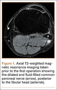
Approximately 7 months after his initial presentation, the patient developed a marked worsening—increased numbness and weakness to ankle dorsiflexion—of his original symptoms. A repeat EMG/nerve conduction study of the lower extremity showed a persistent peroneal nerve neuropathy with a persistent denervation of the extensor hallucis longus, tibialis anterior, and extensor digitorum brevis muscles.
Because of continuing symptoms and increasing pain, the patient had surgery 8 months after his initial presentation. At that time, a markedly thickened peroneal nerve was identified. An incision in the epineural sheath released a clear gelatinous fluid consistent with a ganglion cyst. Through the epineural incision, the nerve was decompressed by manually “milking” the fluid from within the sheath. Approximately 30 mL of mucinous fluid was obtained and sent to pathology. No cells were identified.
Postoperatively, the patient noted a marked improvement in his pain. By 2 weeks postoperatively, the numbness in his foot had resolved. At 6 weeks after surgery, the strength of his tibialis anterior and extensor hallucis longus muscles had improved from 3+ to 4-, and he was free of pain.
At 2 months postoperatively, the patient redeveloped pain and numbness, and noted progressive weakness of his left foot and ankle. A repeat MRI of the left knee showed a dilated tubular structure corresponding to the course of the CPN. Comparison of this MRI with the initial MRI showed that the “prominent vein” was actually the dilated CPN.
He was taken to the operating room again 5 months after his first operation. At this time, the CPN was again noted to be markedly dilated (Figure 2). The nerve was explored and a recurrent branch to the proximal tibiofibular joint was identified and divided (Figures 3, 4). Through the divided branch, the CPN could be decompressed by manually “milking” the nerve in a proximal-to-distal direction, expressing clear gelatinous fluid consistent with a ganglion cyst (Figure 5). Pathology of the excised portion of the recurrent nerve was consistent with an intraneural ganglion cyst.
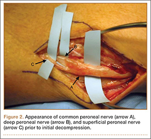
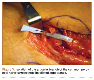
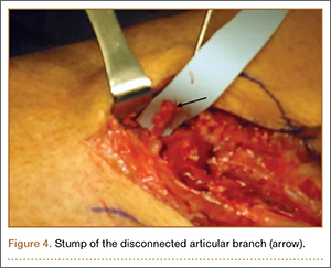
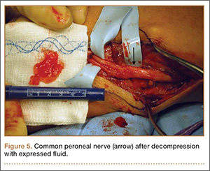
By 2 weeks postoperatively, the numbness of the patient’s left foot had completely resolved, as did his pain. By 3 months after surgery, his extensor hallucis longus strength was 5/5, and ankle dorsiflexion was 4-/5. At 6 months, his ankle dorsiflexion strength was 5/5, and he was completely asymptomatic. At 2 years postoperatively, he remained completely asymptomatic. A follow-up MRI of the left knee showed a ganglion cyst present at the proximal tibiofibular joint with resolution of the intraneural ganglion cyst within the CPN (Figure 6).
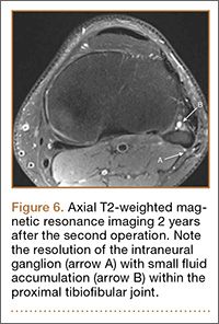
Discussion
Intraneural ganglia of peripheral nerves are relatively rare, most commonly occurring in the CPN.6,8,9 A literature search reveals that this condition is only sparsely reported in orthopedic journals. This report, therefore, describes this rare, yet curable, condition. As noted, without appropriate intervention, the condition has a high likelihood of recurrence with only a brief interruption of symptoms.6,8,9,12
The operative technique delineated in this report relies heavily on research demonstrating that peroneal intraneural ganglia develop from the superior tibiofibular joint and gain access to the CPN via the recurrent articular branch.8,13 Research indicates that such ganglia preferentially proceed proximally along the deep portion of the CPN, within the epineurium.6 This hypothesis was corroborated in our case by the swollen appearance of the CPN proximal to its bifurcation.
Currently, there is no consensus on treatment of intraneural ganglion cysts of the CPN. However, evidence suggests that disconnection of the recurrent branch of the CPN may be important in successfully treating the condition.6,9,14 This unified articular theory was initially proposed by Spinner and colleagues12 in 2003 and recommends that surgical treatment focus on the articular branch as the source of cyst fluid.6,9,12,14 This theory by Spinner and coauthors12,14 was substantiated in our case: Once the articular branch was disconnected, cyst fluid was easily expressed via antegrade massage through the disconnected end. Pathologic analysis of a portion of the detached articular branch is also recommended to rule out other cystic lesions, such as cystic shwannomas.14
The history of the unified articular theory began in the mid-1990s, when Dr. Robert Spinner, board certified in both orthopedic and neurologic surgery, began researching causes of intraneural ganglion cysts. At the time, such ganglia were often treated by radical resection of the nerve and the cyst. Based on his review of literature, and his own cases, Spinner15 developed the theory that, just as with extraneural ganglia, these cysts are fed by fluid from the joint. According to Spinner,9 the sources of such connections were very small articular nerve branches that connect the nerve to the joint. His research led him to the original citation of such an intraneural ganglion of the ulnar nerve, first described by Dr. M. Beauchene, a French physician, in 1810.16 Spinner also discovered that Beauchene’s original dissection specimen had been preserved and was displayed in a medical museum in Paris. When Spinner went to France to view the specimen, he indeed found an intraneural ganglion of the ulnar nerve. On closer inspection, Spinner also discovered a small articular nerve branch containing a “hollow lumen” that would have been capable of allowing the passage of fluid into the nerve and leading to the development of a cyst.16
In our case, in the first operation, a simple incisional decompression of the CPN was performed. Unfortunately, the ganglion cyst quickly recurred, as did the patient’s symptoms. In the second surgical procedure, the articular branch connecting the peroneal nerve to the proximal tibiofibular joint was incised and disconnected from the nerve. This allowed the nerve to be decompressed and prevented a recurrence of the ganglion cyst within the nerve with complete resolution of the patient’s symptoms. This difference alone most likely accounts for the rapid recurrence of symptoms after the initial operation, since the fluid was simply drained, but the source was not detached, allowing the ganglion to recur.6,12,14 This is similar in theory to excising the attachment of a ganglion cyst at the wrist from the underlying joint capsule rather than performing a needle aspiration or puncturing of the cyst.12
Regarding the imaging techniques used to identify intraneural ganglia, it is essential that the surgeon be aware of the unified articular theory and the likely presence of an articular branch. Such branches are extremely small and may be easily missed on imaging and intraoperatively.17,18 MRI is the best method to image these cysts because of its superior ability to visualize soft-tissue lesions.18,19 Intraneural ganglion cysts typically appear as homogenous, lobulated, well-circumscribed masses that are hyperintense on T2-weighted MRI.3,19 Gadolinium may also offer diagnostic utility, because these masses do not enhance with its use on T1-weighted MRI.3,17,19 By employing these techniques, one may easily view most of the ganglion cyst. To image the small articular branch, Spinner and colleagues17 recommend thin-section images with high–spatial resolution T2-imaging. They also advocate obtaining multiple image views and planes to increase the likelihood of successful imaging.17
The applications of the unified articular theory also extend beyond intraneural ganglia of the CPN. While the CPN is the most common location for intraneural ganglion occurrence,6,17,20 cases have also been described of intraneural ganglion cysts of the tibial nerve at the proximal tibiofibular joint, as well as via the posterior tibial and medial plantar nerves at the subtalar joint within the tarsal tunnel.11,18-23 Most cases involving the posterior tibial and medial plantar nerves were found in patients presenting with signs of tarsal tunnel syndrome.22,23 Intraneural ganglia have also been found within the superficial peroneal nerve arising from the inferior tibiofibular joint.20 In certain cases, these ganglia have also been noted to connect to the joint via a small articular branch.19,22 In 1 case of an intraneural ganglion of the tibial nerve at the superior tibiofibular joint, initial conservative surgery led to early recurrence of symptoms.19 Just as in our case, the patient returned to the operating room and, after isolation and ligation of an articular branch, the patient experienced long-term resolution of both the symptoms and the cyst.19
Given the overwhelming evidence in support of the unified articular theory, we agree with the recommendation by Spinner and colleagues19 to search for an articular branch both via preoperative imaging and during the operation itself in all cases of intraneural ganglia. Assuming the mechanism of cyst formation is the same in most cases of intraneural ganglia, one could reasonably apply the same surgical techniques used in our case to the management of all intraneural ganglia, drastically reducing recurrence rates.
Conclusion
Based on research and corroborated by this case, the key to successful operative treatment of a common peroneal intraneural ganglion is division of the recurrent articular branch, which connects the proximal tibiofibular joint to the CPN.6,9,11,12,14 Evidence has shown that disconnecting the articular branch and disrupting the source of the intraneural ganglion can resolve the condition and dramatically diminish the chance of recurrence.6,8,12,14 This has become known as the unified articular theory.6,12,14 Reports also suggest that, without disconnecting this articular branch, intraneural ganglion recurrence rates may be higher than 30%.6,12,14,19 This case, therefore, supports the findings of previous authors9-11,14 and provides an example of successful utilization of the treatment protocol delineated by Spinner and colleagues.10,11
1. Coakley FV, Finlay DB, Harper WM, Allen MJ. Direct and indirect MRI findings in ganglion cysts of the common peroneal nerve. Clin Radiol. 1995;50(3):168-169.
2. Coleman SH, Beredjeklian PK, Weiland AJ. Intraneural ganglion cyst of the peroneal nerve accompanied by complete foot drop. A case report. Am J Sports Med. 2001;29(2):238-241.
3. Dubuisson AS, Stevenaert A. Recurrent ganglion cyst of the peroneal nerve: radiological and operative observations. Case report. J Neurosurg. 1996;84(2):280-283.
4. Lee YS, Kim JE, Kwak JH, Wang IW, Lee BK. Foot drop secondary to peroneal intraneural cyst arising from tibiofibular joint. Knee Surg Sports Traumatol Arthrosc. 2013;21(9):2063-2065.
5. Leijten FS, Arts WF, Puylaert JB. Ultrasound diagnosis of an intraneural ganglion cyst of the peroneal nerve. Case report. J Neurosurg. 1992;76(3):538-540.
6. Spinner RJ, Desy NM, Rock MG, Amrami KK. Peroneal intraneural ganglia. Part I. Techniques for successful diagnosis and treatment. Neurosurg Focus. 2007;22(6):E16.
7. Spinner RJ, Desy NM, Amrami KK. Cystic transverse limb of the articular branch: a pathognomonic sign for peroneal intraneural ganglia at the superior tibiofibular joint. Neurosurgery. 2006;59(1):157-166.
8. Spinner RJ, Carmichael SW, Wang H, Parisi TJ, Skinner JA, Amrami KK. Patterns of intraneural ganglion cyst descent. Clin Anat. 2008;21(3):233-245.
9. Spinner RJ, Atkinson JL, Scheithauer BW, et al. Peroneal intraneural ganglia: the importance of the articular branch. Clinical series. J Neurosurg. 2003;99(2):319-329.
10. Spillane RM, Whitman GJ, Chew FS. Peroneal nerve ganglion cyst. AJR Am J Roentgenol. 1996;166(3):682.
11. Spinner RJ, Hébert-Blouin MN, Amrami KK, Rock MG. Peroneal and tibial intraneural ganglion cysts in the knee region: a technical note. Neurosurgery. 2010;67(3 Suppl Operative):ons71-78.
12. Spinner RJ, Atkinson JL, Tiel RL. Peroneal intraneural ganglia: the importance of the articular branch. A unifying theory. J Neurosurg. 2003;99(2):330-343.
13. Spinner RJ, Amrami KK, Wolanskyj AP, et al. Dynamic phases of peroneal and tibial intraneural ganglia formation: a new dimension added to the unifying articular theory. J Neurosurg. 2007;107(2):296-307.
14. Spinner RJ, Desy NM, Rock MG, Amrami KK. Peroneal intraneural ganglia. Part II. Lessons learned and pitfalls to avoid for successful diagnosis and treatment. Neurosurg Focus. 2007;22(6):E27.
15. Spinner RJ; Mayo Clinic. 200-year-old mystery solved: intraneural ganglion cyst [video]. YouTube. www.youtube.com/watch?v=5Xk4kq-qygg. Published October 13, 2008. Accessed February 23, 2015.
16. Spinner RJ, Vincent JF, Wolanskyj AP, Scheithauer BW. Intraneural ganglion cyst: a 200-year-old mystery solved. Clin Anat. 2008;21(7):611-618.
17. Spinner RJ, Dellon AL, Rosson GD, Anderson SR, Amrami KK. Tibial intraneural ganglia in the tarsal tunnel: Is there a joint connection? J Foot Ankle Surg. 2007;46(1):27-31.
18. Spinner RJ, Amrami KK, Rock MG. The use of MR arthrography to document an occult joint communication in a recurrent peroneal intraneural ganglion. Skeletal Radiol. 2006;35(3):172-179.
19. Spinner RJ, Atkinson JL, Harper CM Jr, Wenger DE. Recurrent intraneural ganglion cyst of the tibial nerve. Case report. J Neurosurg. 2000;92(2):334-337.20. Stamatis ED, Manidakis NE, Patouras PP. Intraneural ganglion of the superficial peroneal nerve: a case report. J Foot Ankle Surg. 2010;49(4):400.e1-4.
21. Patel P, Schucany WG. A rare case of intraneural ganglion cyst involving the tibial nerve. Proc (Bayl Univ Med Cent). 2012;25(2):132-135.
22. Høgh J. Benign cystic lesions of peripheral nerves. Int Orthop. 1988;12(4):269-271.
23. Poppi M, Giuliani G, Pozzati E, Acciarri N, Forti A. Tarsal tunnel syndrome secondary to intraneural ganglion. J Neurol Neurosurg Psychiatr. 1989;52(8):1014-1015.
Intraneural ganglion cysts of peripheral nerves occurring within the epineural sheath are rare.1-7 Case reports exist primarily within the neurosurgical literature, but very little in the orthopedic literature describes this condition. The peripheral nerve most commonly affected by an intraneural ganglion is the common peroneal nerve (CPN).2,8,9 Such ganglia most often afflict middle-aged men with a history of micro- or macro-trauma and present with typical clinical manifestations of calf pain and progressive symptoms of ipsilateral foot drop and lower leg paresthesia.2-5,10-12 The mechanism by which these ganglia form is not well understood and, as a result, treatment options are debated.6 Recent development of a “unified articular theory,” suggests that such intraneural ganglia of the CPN are fed by a small, recurrent articular branch of the CPN.6,12,13 Cadaveric studies indicate that this branch originates from the deep peroneal nerve, just millimeters distal to the bifurcation of the CPN, and extends to the superior tibiofibular joint, providing direct access for cyst fluid to enter the CPN following the path of least resistance.7,8,12,14 Therefore, according to the unified articular theory, the recommended treatment involves division of the articular branch, allowing the ganglion to be decompressed.6
We present a case of a 41-year-old man with an intraneural ganglion cyst of the CPN who was successfully treated, according to the recommendations of the unified articular theory. It is important for orthopedic surgeons to read about and recognize this condition, because knowledge of the operative technique outlined in our report allows it to be treated quite effectively. The patient provided written informed consent for print and electronic publication of this case report.
Case Report
A 41-year-old man presented with a 2-month history of traumatic left lateral knee pain with numbness and weakness to the left foot and ankle. Initial examination showed a mild restriction of lumbosacral range of motion, with no complaints of lower back pain. Sciatic root stretch signs were negative. Strength testing of the lower extremities revealed 3+/5 strength of ankle dorsiflexion and great toe extension on the left side. There was a mild alteration in sensation to light touch on the lateral side of the left foot. Tenderness, without swelling, was present around the left fibular head. There was a positive Tinel sign over the peroneal nerve at the level of the fibular neck.
The patient was initially treated with anti-inflammatories and activity modification. An electromyogram (EMG)/nerve conduction study of the lower extremity showed a left peroneal nerve neurapraxia at the level of the fibular head. Noncontrast magnetic resonance imaging (MRI) of the left knee showed a “slightly prominent vein coursing posterior to the fibular head near the expected location of the common peroneal nerve,” according to the radiologist’s notes (Figure 1). The patient exhibited improvement with use of anti-inflammatories over several months. There was an increase in his ankle dorsiflexion strength to 4/5 and improvement in his pain and numbness.
Approximately 7 months after his initial presentation, the patient developed a marked worsening—increased numbness and weakness to ankle dorsiflexion—of his original symptoms. A repeat EMG/nerve conduction study of the lower extremity showed a persistent peroneal nerve neuropathy with a persistent denervation of the extensor hallucis longus, tibialis anterior, and extensor digitorum brevis muscles.
Because of continuing symptoms and increasing pain, the patient had surgery 8 months after his initial presentation. At that time, a markedly thickened peroneal nerve was identified. An incision in the epineural sheath released a clear gelatinous fluid consistent with a ganglion cyst. Through the epineural incision, the nerve was decompressed by manually “milking” the fluid from within the sheath. Approximately 30 mL of mucinous fluid was obtained and sent to pathology. No cells were identified.
Postoperatively, the patient noted a marked improvement in his pain. By 2 weeks postoperatively, the numbness in his foot had resolved. At 6 weeks after surgery, the strength of his tibialis anterior and extensor hallucis longus muscles had improved from 3+ to 4-, and he was free of pain.
At 2 months postoperatively, the patient redeveloped pain and numbness, and noted progressive weakness of his left foot and ankle. A repeat MRI of the left knee showed a dilated tubular structure corresponding to the course of the CPN. Comparison of this MRI with the initial MRI showed that the “prominent vein” was actually the dilated CPN.
He was taken to the operating room again 5 months after his first operation. At this time, the CPN was again noted to be markedly dilated (Figure 2). The nerve was explored and a recurrent branch to the proximal tibiofibular joint was identified and divided (Figures 3, 4). Through the divided branch, the CPN could be decompressed by manually “milking” the nerve in a proximal-to-distal direction, expressing clear gelatinous fluid consistent with a ganglion cyst (Figure 5). Pathology of the excised portion of the recurrent nerve was consistent with an intraneural ganglion cyst.
By 2 weeks postoperatively, the numbness of the patient’s left foot had completely resolved, as did his pain. By 3 months after surgery, his extensor hallucis longus strength was 5/5, and ankle dorsiflexion was 4-/5. At 6 months, his ankle dorsiflexion strength was 5/5, and he was completely asymptomatic. At 2 years postoperatively, he remained completely asymptomatic. A follow-up MRI of the left knee showed a ganglion cyst present at the proximal tibiofibular joint with resolution of the intraneural ganglion cyst within the CPN (Figure 6).
Discussion
Intraneural ganglia of peripheral nerves are relatively rare, most commonly occurring in the CPN.6,8,9 A literature search reveals that this condition is only sparsely reported in orthopedic journals. This report, therefore, describes this rare, yet curable, condition. As noted, without appropriate intervention, the condition has a high likelihood of recurrence with only a brief interruption of symptoms.6,8,9,12
The operative technique delineated in this report relies heavily on research demonstrating that peroneal intraneural ganglia develop from the superior tibiofibular joint and gain access to the CPN via the recurrent articular branch.8,13 Research indicates that such ganglia preferentially proceed proximally along the deep portion of the CPN, within the epineurium.6 This hypothesis was corroborated in our case by the swollen appearance of the CPN proximal to its bifurcation.
Currently, there is no consensus on treatment of intraneural ganglion cysts of the CPN. However, evidence suggests that disconnection of the recurrent branch of the CPN may be important in successfully treating the condition.6,9,14 This unified articular theory was initially proposed by Spinner and colleagues12 in 2003 and recommends that surgical treatment focus on the articular branch as the source of cyst fluid.6,9,12,14 This theory by Spinner and coauthors12,14 was substantiated in our case: Once the articular branch was disconnected, cyst fluid was easily expressed via antegrade massage through the disconnected end. Pathologic analysis of a portion of the detached articular branch is also recommended to rule out other cystic lesions, such as cystic shwannomas.14
The history of the unified articular theory began in the mid-1990s, when Dr. Robert Spinner, board certified in both orthopedic and neurologic surgery, began researching causes of intraneural ganglion cysts. At the time, such ganglia were often treated by radical resection of the nerve and the cyst. Based on his review of literature, and his own cases, Spinner15 developed the theory that, just as with extraneural ganglia, these cysts are fed by fluid from the joint. According to Spinner,9 the sources of such connections were very small articular nerve branches that connect the nerve to the joint. His research led him to the original citation of such an intraneural ganglion of the ulnar nerve, first described by Dr. M. Beauchene, a French physician, in 1810.16 Spinner also discovered that Beauchene’s original dissection specimen had been preserved and was displayed in a medical museum in Paris. When Spinner went to France to view the specimen, he indeed found an intraneural ganglion of the ulnar nerve. On closer inspection, Spinner also discovered a small articular nerve branch containing a “hollow lumen” that would have been capable of allowing the passage of fluid into the nerve and leading to the development of a cyst.16
In our case, in the first operation, a simple incisional decompression of the CPN was performed. Unfortunately, the ganglion cyst quickly recurred, as did the patient’s symptoms. In the second surgical procedure, the articular branch connecting the peroneal nerve to the proximal tibiofibular joint was incised and disconnected from the nerve. This allowed the nerve to be decompressed and prevented a recurrence of the ganglion cyst within the nerve with complete resolution of the patient’s symptoms. This difference alone most likely accounts for the rapid recurrence of symptoms after the initial operation, since the fluid was simply drained, but the source was not detached, allowing the ganglion to recur.6,12,14 This is similar in theory to excising the attachment of a ganglion cyst at the wrist from the underlying joint capsule rather than performing a needle aspiration or puncturing of the cyst.12
Regarding the imaging techniques used to identify intraneural ganglia, it is essential that the surgeon be aware of the unified articular theory and the likely presence of an articular branch. Such branches are extremely small and may be easily missed on imaging and intraoperatively.17,18 MRI is the best method to image these cysts because of its superior ability to visualize soft-tissue lesions.18,19 Intraneural ganglion cysts typically appear as homogenous, lobulated, well-circumscribed masses that are hyperintense on T2-weighted MRI.3,19 Gadolinium may also offer diagnostic utility, because these masses do not enhance with its use on T1-weighted MRI.3,17,19 By employing these techniques, one may easily view most of the ganglion cyst. To image the small articular branch, Spinner and colleagues17 recommend thin-section images with high–spatial resolution T2-imaging. They also advocate obtaining multiple image views and planes to increase the likelihood of successful imaging.17
The applications of the unified articular theory also extend beyond intraneural ganglia of the CPN. While the CPN is the most common location for intraneural ganglion occurrence,6,17,20 cases have also been described of intraneural ganglion cysts of the tibial nerve at the proximal tibiofibular joint, as well as via the posterior tibial and medial plantar nerves at the subtalar joint within the tarsal tunnel.11,18-23 Most cases involving the posterior tibial and medial plantar nerves were found in patients presenting with signs of tarsal tunnel syndrome.22,23 Intraneural ganglia have also been found within the superficial peroneal nerve arising from the inferior tibiofibular joint.20 In certain cases, these ganglia have also been noted to connect to the joint via a small articular branch.19,22 In 1 case of an intraneural ganglion of the tibial nerve at the superior tibiofibular joint, initial conservative surgery led to early recurrence of symptoms.19 Just as in our case, the patient returned to the operating room and, after isolation and ligation of an articular branch, the patient experienced long-term resolution of both the symptoms and the cyst.19
Given the overwhelming evidence in support of the unified articular theory, we agree with the recommendation by Spinner and colleagues19 to search for an articular branch both via preoperative imaging and during the operation itself in all cases of intraneural ganglia. Assuming the mechanism of cyst formation is the same in most cases of intraneural ganglia, one could reasonably apply the same surgical techniques used in our case to the management of all intraneural ganglia, drastically reducing recurrence rates.
Conclusion
Based on research and corroborated by this case, the key to successful operative treatment of a common peroneal intraneural ganglion is division of the recurrent articular branch, which connects the proximal tibiofibular joint to the CPN.6,9,11,12,14 Evidence has shown that disconnecting the articular branch and disrupting the source of the intraneural ganglion can resolve the condition and dramatically diminish the chance of recurrence.6,8,12,14 This has become known as the unified articular theory.6,12,14 Reports also suggest that, without disconnecting this articular branch, intraneural ganglion recurrence rates may be higher than 30%.6,12,14,19 This case, therefore, supports the findings of previous authors9-11,14 and provides an example of successful utilization of the treatment protocol delineated by Spinner and colleagues.10,11
1. Coakley FV, Finlay DB, Harper WM, Allen MJ. Direct and indirect MRI findings in ganglion cysts of the common peroneal nerve. Clin Radiol. 1995;50(3):168-169.
2. Coleman SH, Beredjeklian PK, Weiland AJ. Intraneural ganglion cyst of the peroneal nerve accompanied by complete foot drop. A case report. Am J Sports Med. 2001;29(2):238-241.
3. Dubuisson AS, Stevenaert A. Recurrent ganglion cyst of the peroneal nerve: radiological and operative observations. Case report. J Neurosurg. 1996;84(2):280-283.
4. Lee YS, Kim JE, Kwak JH, Wang IW, Lee BK. Foot drop secondary to peroneal intraneural cyst arising from tibiofibular joint. Knee Surg Sports Traumatol Arthrosc. 2013;21(9):2063-2065.
5. Leijten FS, Arts WF, Puylaert JB. Ultrasound diagnosis of an intraneural ganglion cyst of the peroneal nerve. Case report. J Neurosurg. 1992;76(3):538-540.
6. Spinner RJ, Desy NM, Rock MG, Amrami KK. Peroneal intraneural ganglia. Part I. Techniques for successful diagnosis and treatment. Neurosurg Focus. 2007;22(6):E16.
7. Spinner RJ, Desy NM, Amrami KK. Cystic transverse limb of the articular branch: a pathognomonic sign for peroneal intraneural ganglia at the superior tibiofibular joint. Neurosurgery. 2006;59(1):157-166.
8. Spinner RJ, Carmichael SW, Wang H, Parisi TJ, Skinner JA, Amrami KK. Patterns of intraneural ganglion cyst descent. Clin Anat. 2008;21(3):233-245.
9. Spinner RJ, Atkinson JL, Scheithauer BW, et al. Peroneal intraneural ganglia: the importance of the articular branch. Clinical series. J Neurosurg. 2003;99(2):319-329.
10. Spillane RM, Whitman GJ, Chew FS. Peroneal nerve ganglion cyst. AJR Am J Roentgenol. 1996;166(3):682.
11. Spinner RJ, Hébert-Blouin MN, Amrami KK, Rock MG. Peroneal and tibial intraneural ganglion cysts in the knee region: a technical note. Neurosurgery. 2010;67(3 Suppl Operative):ons71-78.
12. Spinner RJ, Atkinson JL, Tiel RL. Peroneal intraneural ganglia: the importance of the articular branch. A unifying theory. J Neurosurg. 2003;99(2):330-343.
13. Spinner RJ, Amrami KK, Wolanskyj AP, et al. Dynamic phases of peroneal and tibial intraneural ganglia formation: a new dimension added to the unifying articular theory. J Neurosurg. 2007;107(2):296-307.
14. Spinner RJ, Desy NM, Rock MG, Amrami KK. Peroneal intraneural ganglia. Part II. Lessons learned and pitfalls to avoid for successful diagnosis and treatment. Neurosurg Focus. 2007;22(6):E27.
15. Spinner RJ; Mayo Clinic. 200-year-old mystery solved: intraneural ganglion cyst [video]. YouTube. www.youtube.com/watch?v=5Xk4kq-qygg. Published October 13, 2008. Accessed February 23, 2015.
16. Spinner RJ, Vincent JF, Wolanskyj AP, Scheithauer BW. Intraneural ganglion cyst: a 200-year-old mystery solved. Clin Anat. 2008;21(7):611-618.
17. Spinner RJ, Dellon AL, Rosson GD, Anderson SR, Amrami KK. Tibial intraneural ganglia in the tarsal tunnel: Is there a joint connection? J Foot Ankle Surg. 2007;46(1):27-31.
18. Spinner RJ, Amrami KK, Rock MG. The use of MR arthrography to document an occult joint communication in a recurrent peroneal intraneural ganglion. Skeletal Radiol. 2006;35(3):172-179.
19. Spinner RJ, Atkinson JL, Harper CM Jr, Wenger DE. Recurrent intraneural ganglion cyst of the tibial nerve. Case report. J Neurosurg. 2000;92(2):334-337.20. Stamatis ED, Manidakis NE, Patouras PP. Intraneural ganglion of the superficial peroneal nerve: a case report. J Foot Ankle Surg. 2010;49(4):400.e1-4.
21. Patel P, Schucany WG. A rare case of intraneural ganglion cyst involving the tibial nerve. Proc (Bayl Univ Med Cent). 2012;25(2):132-135.
22. Høgh J. Benign cystic lesions of peripheral nerves. Int Orthop. 1988;12(4):269-271.
23. Poppi M, Giuliani G, Pozzati E, Acciarri N, Forti A. Tarsal tunnel syndrome secondary to intraneural ganglion. J Neurol Neurosurg Psychiatr. 1989;52(8):1014-1015.
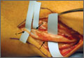
Using Wearable Technology to Record Surgical Videos
Safe and efficient advanced surgical skill training is of tremendous importance. With the recent increase in Internet use for medical education, there has been a concomitant increase in video recording of surgical procedures and techniques. Surgical recordings have been used in a variety of ways—as live webcasts for remote participants, as “coaching” opportunities for surgeons evaluating their own performance in the operating room, and even as informational resources for patients about to undergo the same surgery.
Surgical multimedia is being delivered through several different outlets. Many academic conferences and meetings showcase videos of different procedures, and several subspecialty societies (eg, Arthroscopy Association of North America) house archives of technical videos for viewing by members. In addition, the VuMedi website offers videos and allows members to comment on them and interact with the videographers. Surgeons are even posting technique videos on YouTube and other public websites.
A large proportion of surgical multimedia is recorded with conventional high-definition video cameras.1 Besides being able to experience a case at any time and from outside the operating room, the audience can watch from numerous vantage points, angles, and zoom levels. Also, surgeons’ narration can be valuable in helping the audience follow along with the case.
Recording surgical multimedia historically required tight coordination and precise planning by surgeon and videographer. However, innovations in wearable technology now allow surgeons to literally wear video cameras and record procedures as they perform them, in real time—to act as both surgeon and videographer.
Two such products are Google Glass (Google, Mountain View, California) and GoPro Hero (GoPro, San Mateo, California), both of which allow surgeons to record exactly what they see during procedures (Figure 1). Using a wearable technology for surgical multimedia creation requires a deep familiarity with its capabilities and limitations. In this article, we summarize these products’ similarities and differences and provide a technical overview for using wearable technologies in surgical multimedia creation.
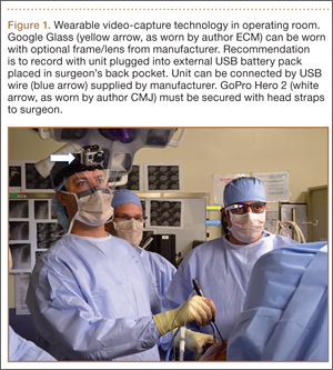
1. Choosing a device
When purchasing either wearable device, several factors must be considered, including budget, possible uses outside the operating room, and possible limitations of the technology (Table 1). At this time, Google Glass is significantly more expensive than GoPro Hero. The Google Glass base unit costs $1500, and the GoPro Hero 3 model costs approximately $200 (higher-priced Hero models are available). Both devices require accessories (eg, portable battery unit, dedicated hard drive).
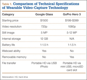
Device capabilities must also be considered (Table 2). Google Glass consists of both hardware and software. Users can record what is seen and heard through the lens and then use apps to create text and e-mail portals to online gaming, social media, and even golf-course GPS. The app market for Google Glass is nascent but undoubtedly will increase in volume and scope as more users adopt the technology (Google Glass comes with both Bluetooth and Wi-Fi and can function tethered through a smartphone). GoPro is mainly a hardware unit that can record in various settings (it is popular with athletes who want to capture and broadcast their participation in action sports). Newer GoPro Hero versions offer Wi-Fi, which allows streaming of video content to a smartphone or tablet through an app. Having clearly defined goals for a device—as they pertain to use outside the operating room, such as outdoor activities and underwater recording—may help the surgeon decide which product is more suitable. Last, it is important to consider limitations. Google Glass resolution is 720p (1280×720) for video and 5 MP for still images, and GoPro resolution can reach 1080p (1920×1080) for video and 5 MP for stills.
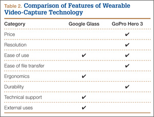
Both devices require purchase of accessories. An external USB battery pack is useful for both devices, as is a password-encrypted hard drive for media storage. Lenswear does not come with the base version of Google Glass and is purchased separately from the company. GoPro users buy micro SD cards (~$50 per 64-GB high-speed transfer card) for storage on the device and may buy lithium-ion batteries as an alternative to the external USB battery pack.
Author Update
In January 2015, Google announced that it was temporarily suspending its “Explorer” program, which allowed individual users to buy and test the device for personal use. However, Google is continuing its development of Glass with health care technology, among other areas of growth and development.2,3
2. Recording a successful surgical video
Unlike a camcorder, which typically is set on a tripod for conventional video recording of surgery, Google Glass and GoPro are intricately linked to the operator. Surgeons must be constantly aware of where they are during surgery and try not to let anything obstruct the camera’s view.
Before starting a case, the surgeon using either device must ensure that its battery is fully charged, as a full charge typically supports 1 hour of continuous recording (the Google Glass battery is a lithium-ion 670-mAh internal unit). A full charge should be enough to capture a short case. Newer GoPro models, with a battery listed at 1050 mAh, provide 1 to 2 hours of recording. When more than 1 hour is needed, an external USB battery pack can be used. This pack allows the device to remain plugged in throughout the case (the pack is kept in the surgeon’s back pocket). We recommend having an external battery pack that is at least 10,000 mAh (~$30 online retail), which easily provides 3+ hours of recording. Unfortunately, this arrangement can be cumbersome. Alternatively, with GoPro, additional batteries may be purchased, but the user needs to dismount the device in order to swap them in (may be difficult during surgery). With both units, partitioning a video into shorter segments conserves battery power and minimizes the risk of file corruption, which may occur if the battery dies or the device overheats.
Google Glass users can bypass manual operation of the device by giving it voice commands (eg, start video, take still image). The exception is for recording video for more than 10 seconds (current default setting). Unfortunately, the surgeon must touch the device to start this recording, which means using extra gloves to preserve operating field sterility. Still images can be made through a combination of voice and head gestures and without manual intervention (Figure 2). Last, users must ensure that the device is not actively connected through Bluetooth to a mobile phone, as incoming calls, text messages, and e-mails may disrupt active recording and become a distraction. The connection can be deactivated by disabling Bluetooth on the host smartphone or by placing the phone into airplane mode and turning off Wi-Fi.
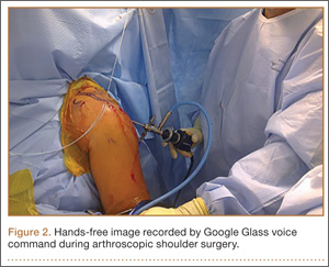
Google Glass users can see what is being recorded through the viewfinder prism, whereas GoPro requires precise framing of the video before recording. Framing is done by grossly aiming the device in the desired direction. However, there is no way to ensure exact aim during recording. If at any point during a case there is slight repositioning of the GoPro, there is a risk of recording the case out of the center of view. An important advantage to newer GoPro versions is the ability to control the device through a wireless remote that can be placed under the surgeon’s gown. The remote can be used to pause and resume recording, without changing gloves, as is done with Google Glass. Last, because the minimum viewing distance from the surgical field is usually 18 inches or more, typically there is no loss of focus or blurring of the image from short-distance recording on either device.
3. File management and playback
Before using wearable technology in the operating room, surgeons must become aware of its limitations with respect to file storage and playback. Google Glass has a usable memory of about 12 GB (1 hour of video may require 1.5-2.0 GB). Conversely, GoPro’s capacity is defined by the micro SD card used. Therefore, the Google Glass hard drive must be regularly maintained well before being brought into the operating room, whereas recording can be extended (with respect to memory) for the GoPro if the media card is large enough.
Both devices allow for wired file transfer, which may be done with Windows Explorer (PC) or iPhoto (Macintosh). However, Google Glass also allows for wireless transfer, through portable storage supported by Google. Although this type of file transfer may be convenient for short, everyday clips made outside the operating room, it is prohibitive for surgical media, mainly because of patient privacy concerns. With wireless transfer to a nonsecure cloud platform, there is a risk of breach of patient confidentiality. We therefore recommend against using wireless upload when producing surgical multimedia, as patient identifiers are likely to be included in the recorded audio or video contents. Conversely, with GoPro, the micro SD card can be used as a portable hard drive to transfer files to a laptop or media reader, obviating the need for wired or wireless transmission. Last, when using traditional wire transfer or memory card to upload to a hard drive, users must ensure that the drive complies with patient privacy laws and regulations.
4. Privacy and patient consent
As mentioned, great care must be taken to ensure that patient privacy laws are followed. This is especially relevant with content uploaded to online cloud storage, as with Google Glass. The upload may occur automatically if the unit is connected to a Wi-Fi hotspot. In addition, when using surgical media for a real-time webcast for education or demonstration purposes, surgeons must ensure that no protected health information is broadcast and that the patient and the surgical team are aware of the webcast and its purposes.
Before using wearable technology during patient care, patient consent must be obtained. Surgeons should ask the patient to consent to video recording of surgery or an encounter (eg, clinic visit) for education purposes. Our institution’s consent form includes a section for this particular type of consent. If an institution’s form lacks such a section, surgeons should consult their risk management department to ensure there is a proper avenue for obtaining patient consent to record the procedure or encounter. A separate, dedicated media consent form may be required. Last, whoever operates a wearable device should be careful to use the device only during encounters that have received explicit recording consent—as opposed to wearing the device in the hallways or elsewhere in the hospital, where protected health information might be inadvertently recorded.4
5. Putting it all to use
After successful recording of surgery, an effort should be made to produce a high-quality video for education or demonstration purposes. Unfortunately, there is no built-in optical zooming with Google Glass or GoPro, and recording segments in which surgeons focus on detailed anatomy (with high-quality zoom) may prove difficult. Online descriptions of do-it-yourself modifications to place zoom capability on GoPro devices may be useful in surgical video recording, particularly for small surgical fields (hand or foot surgery). In addition, footage may be zoomed in on during postprocessing (Figure 3), though some resolution will be lost in the editing.
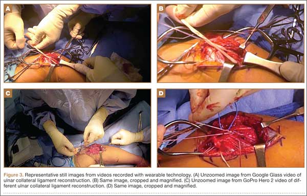
There is no practical way to incorporate Google Glass or GoPro while using surgical loupes or a surgical microscope. As a result, videos recorded with wearable technology may not reach the minimum resolution needed for useful surgical technique videos, as these traditionally are produced on high-definition camcorders with optical zoom, allowing detailed viewing of anatomical structures without resolution loss through digital zoom or postprocessing editing.
There has been tremendous benefit in incorporating wearable technology into our practice. Videos made with Google Glass and GoPro have been successfully used for surgical preparation and training, allowing orthopedic surgical residents to rehearse surgery before participating in it. Alternatively, having used Google Glass or GoPro to record a case, residents have then been able to review each surgical step on video—thereby reinforcing their knowledge of the steps, techniques, pearls, and pitfalls before performing the surgery again. Footage from surgeries recorded with Google Glass and GoPro has also been shown at weekly technique-focused conferences, allowing surgeons to analyze particular steps and highlight applicable learning points. Last, attending surgeons in our practice have used wearable technology in “coaching” mode, either reviewing case footage to identify areas for improvement or sharing footage with senior surgeons in order to elicit feedback and suggestions for possible improvement.
As new iterations of wearable video technology come to market, with advancements in both hardware and software, surgeons may be able to enhance education and teaching through seamless recording of surgical procedures. Use of wearable technology may also begin to extend beyond the operating room—to outpatient settings, such as preoperative and postoperative physical examinations. The latest versions of Google Glass and GoPro Hero allow surgeons to record surgical procedures with relative ease, without the personnel, equipment, and coordination required for traditional surgical videography.
Video 1. Coracoid harvest for transfer during Latarjet procedure performed and filmed by Dr. Jobin using GoPro Hero 3.
The video associated with this article is no longer available on this site. Please view all of our videos on the MDedge YouTube channel
Video 2. Distal biceps repair performed by Dr. Makhni and Dr. Jobin, filmed by Dr. Makhni using Google Glass.
The video associated with this article is no longer available on this site. Please view all of our videos on the MDedge YouTube channel
1. Leahy M. Creating a good surgical technique video. AAOS Now. 2010;4(11). http://www.aaos.org/news/aaosnow/nov10/clinical4.asp. Accessed February 15, 2015.
2. Google Glass sales halted but firm says kit is not dead. BBC News website. http://www.bbc.com/news/technology-30831128. Published January 15, 2015. Accessed February 18, 2015.
3. Metz C. Sorry, but Google Glass isn’t anywhere close to dead. Wired website. http://www.wired.com/2015/02/sorry-google-glass-isnt-anywhere-close-dead/. Published February 8, 2015. Accessed February 18, 2015.
4. Peregrin T. Surgeons see future applications for Google Glass. Bull Am Coll Surg. 2014;99(7):9-16. http://bulletin.facs.org/2014/07/surgeons-see-future-applications-for-google-glass/#.U8SLKZaJAyZ.twitter. Accessed February 15, 2015.
Safe and efficient advanced surgical skill training is of tremendous importance. With the recent increase in Internet use for medical education, there has been a concomitant increase in video recording of surgical procedures and techniques. Surgical recordings have been used in a variety of ways—as live webcasts for remote participants, as “coaching” opportunities for surgeons evaluating their own performance in the operating room, and even as informational resources for patients about to undergo the same surgery.
Surgical multimedia is being delivered through several different outlets. Many academic conferences and meetings showcase videos of different procedures, and several subspecialty societies (eg, Arthroscopy Association of North America) house archives of technical videos for viewing by members. In addition, the VuMedi website offers videos and allows members to comment on them and interact with the videographers. Surgeons are even posting technique videos on YouTube and other public websites.
A large proportion of surgical multimedia is recorded with conventional high-definition video cameras.1 Besides being able to experience a case at any time and from outside the operating room, the audience can watch from numerous vantage points, angles, and zoom levels. Also, surgeons’ narration can be valuable in helping the audience follow along with the case.
Recording surgical multimedia historically required tight coordination and precise planning by surgeon and videographer. However, innovations in wearable technology now allow surgeons to literally wear video cameras and record procedures as they perform them, in real time—to act as both surgeon and videographer.
Two such products are Google Glass (Google, Mountain View, California) and GoPro Hero (GoPro, San Mateo, California), both of which allow surgeons to record exactly what they see during procedures (Figure 1). Using a wearable technology for surgical multimedia creation requires a deep familiarity with its capabilities and limitations. In this article, we summarize these products’ similarities and differences and provide a technical overview for using wearable technologies in surgical multimedia creation.
1. Choosing a device
When purchasing either wearable device, several factors must be considered, including budget, possible uses outside the operating room, and possible limitations of the technology (Table 1). At this time, Google Glass is significantly more expensive than GoPro Hero. The Google Glass base unit costs $1500, and the GoPro Hero 3 model costs approximately $200 (higher-priced Hero models are available). Both devices require accessories (eg, portable battery unit, dedicated hard drive).
Device capabilities must also be considered (Table 2). Google Glass consists of both hardware and software. Users can record what is seen and heard through the lens and then use apps to create text and e-mail portals to online gaming, social media, and even golf-course GPS. The app market for Google Glass is nascent but undoubtedly will increase in volume and scope as more users adopt the technology (Google Glass comes with both Bluetooth and Wi-Fi and can function tethered through a smartphone). GoPro is mainly a hardware unit that can record in various settings (it is popular with athletes who want to capture and broadcast their participation in action sports). Newer GoPro Hero versions offer Wi-Fi, which allows streaming of video content to a smartphone or tablet through an app. Having clearly defined goals for a device—as they pertain to use outside the operating room, such as outdoor activities and underwater recording—may help the surgeon decide which product is more suitable. Last, it is important to consider limitations. Google Glass resolution is 720p (1280×720) for video and 5 MP for still images, and GoPro resolution can reach 1080p (1920×1080) for video and 5 MP for stills.
Both devices require purchase of accessories. An external USB battery pack is useful for both devices, as is a password-encrypted hard drive for media storage. Lenswear does not come with the base version of Google Glass and is purchased separately from the company. GoPro users buy micro SD cards (~$50 per 64-GB high-speed transfer card) for storage on the device and may buy lithium-ion batteries as an alternative to the external USB battery pack.
Author Update
In January 2015, Google announced that it was temporarily suspending its “Explorer” program, which allowed individual users to buy and test the device for personal use. However, Google is continuing its development of Glass with health care technology, among other areas of growth and development.2,3
2. Recording a successful surgical video
Unlike a camcorder, which typically is set on a tripod for conventional video recording of surgery, Google Glass and GoPro are intricately linked to the operator. Surgeons must be constantly aware of where they are during surgery and try not to let anything obstruct the camera’s view.
Before starting a case, the surgeon using either device must ensure that its battery is fully charged, as a full charge typically supports 1 hour of continuous recording (the Google Glass battery is a lithium-ion 670-mAh internal unit). A full charge should be enough to capture a short case. Newer GoPro models, with a battery listed at 1050 mAh, provide 1 to 2 hours of recording. When more than 1 hour is needed, an external USB battery pack can be used. This pack allows the device to remain plugged in throughout the case (the pack is kept in the surgeon’s back pocket). We recommend having an external battery pack that is at least 10,000 mAh (~$30 online retail), which easily provides 3+ hours of recording. Unfortunately, this arrangement can be cumbersome. Alternatively, with GoPro, additional batteries may be purchased, but the user needs to dismount the device in order to swap them in (may be difficult during surgery). With both units, partitioning a video into shorter segments conserves battery power and minimizes the risk of file corruption, which may occur if the battery dies or the device overheats.
Google Glass users can bypass manual operation of the device by giving it voice commands (eg, start video, take still image). The exception is for recording video for more than 10 seconds (current default setting). Unfortunately, the surgeon must touch the device to start this recording, which means using extra gloves to preserve operating field sterility. Still images can be made through a combination of voice and head gestures and without manual intervention (Figure 2). Last, users must ensure that the device is not actively connected through Bluetooth to a mobile phone, as incoming calls, text messages, and e-mails may disrupt active recording and become a distraction. The connection can be deactivated by disabling Bluetooth on the host smartphone or by placing the phone into airplane mode and turning off Wi-Fi.
Google Glass users can see what is being recorded through the viewfinder prism, whereas GoPro requires precise framing of the video before recording. Framing is done by grossly aiming the device in the desired direction. However, there is no way to ensure exact aim during recording. If at any point during a case there is slight repositioning of the GoPro, there is a risk of recording the case out of the center of view. An important advantage to newer GoPro versions is the ability to control the device through a wireless remote that can be placed under the surgeon’s gown. The remote can be used to pause and resume recording, without changing gloves, as is done with Google Glass. Last, because the minimum viewing distance from the surgical field is usually 18 inches or more, typically there is no loss of focus or blurring of the image from short-distance recording on either device.
3. File management and playback
Before using wearable technology in the operating room, surgeons must become aware of its limitations with respect to file storage and playback. Google Glass has a usable memory of about 12 GB (1 hour of video may require 1.5-2.0 GB). Conversely, GoPro’s capacity is defined by the micro SD card used. Therefore, the Google Glass hard drive must be regularly maintained well before being brought into the operating room, whereas recording can be extended (with respect to memory) for the GoPro if the media card is large enough.
Both devices allow for wired file transfer, which may be done with Windows Explorer (PC) or iPhoto (Macintosh). However, Google Glass also allows for wireless transfer, through portable storage supported by Google. Although this type of file transfer may be convenient for short, everyday clips made outside the operating room, it is prohibitive for surgical media, mainly because of patient privacy concerns. With wireless transfer to a nonsecure cloud platform, there is a risk of breach of patient confidentiality. We therefore recommend against using wireless upload when producing surgical multimedia, as patient identifiers are likely to be included in the recorded audio or video contents. Conversely, with GoPro, the micro SD card can be used as a portable hard drive to transfer files to a laptop or media reader, obviating the need for wired or wireless transmission. Last, when using traditional wire transfer or memory card to upload to a hard drive, users must ensure that the drive complies with patient privacy laws and regulations.
4. Privacy and patient consent
As mentioned, great care must be taken to ensure that patient privacy laws are followed. This is especially relevant with content uploaded to online cloud storage, as with Google Glass. The upload may occur automatically if the unit is connected to a Wi-Fi hotspot. In addition, when using surgical media for a real-time webcast for education or demonstration purposes, surgeons must ensure that no protected health information is broadcast and that the patient and the surgical team are aware of the webcast and its purposes.
Before using wearable technology during patient care, patient consent must be obtained. Surgeons should ask the patient to consent to video recording of surgery or an encounter (eg, clinic visit) for education purposes. Our institution’s consent form includes a section for this particular type of consent. If an institution’s form lacks such a section, surgeons should consult their risk management department to ensure there is a proper avenue for obtaining patient consent to record the procedure or encounter. A separate, dedicated media consent form may be required. Last, whoever operates a wearable device should be careful to use the device only during encounters that have received explicit recording consent—as opposed to wearing the device in the hallways or elsewhere in the hospital, where protected health information might be inadvertently recorded.4
5. Putting it all to use
After successful recording of surgery, an effort should be made to produce a high-quality video for education or demonstration purposes. Unfortunately, there is no built-in optical zooming with Google Glass or GoPro, and recording segments in which surgeons focus on detailed anatomy (with high-quality zoom) may prove difficult. Online descriptions of do-it-yourself modifications to place zoom capability on GoPro devices may be useful in surgical video recording, particularly for small surgical fields (hand or foot surgery). In addition, footage may be zoomed in on during postprocessing (Figure 3), though some resolution will be lost in the editing.
There is no practical way to incorporate Google Glass or GoPro while using surgical loupes or a surgical microscope. As a result, videos recorded with wearable technology may not reach the minimum resolution needed for useful surgical technique videos, as these traditionally are produced on high-definition camcorders with optical zoom, allowing detailed viewing of anatomical structures without resolution loss through digital zoom or postprocessing editing.
There has been tremendous benefit in incorporating wearable technology into our practice. Videos made with Google Glass and GoPro have been successfully used for surgical preparation and training, allowing orthopedic surgical residents to rehearse surgery before participating in it. Alternatively, having used Google Glass or GoPro to record a case, residents have then been able to review each surgical step on video—thereby reinforcing their knowledge of the steps, techniques, pearls, and pitfalls before performing the surgery again. Footage from surgeries recorded with Google Glass and GoPro has also been shown at weekly technique-focused conferences, allowing surgeons to analyze particular steps and highlight applicable learning points. Last, attending surgeons in our practice have used wearable technology in “coaching” mode, either reviewing case footage to identify areas for improvement or sharing footage with senior surgeons in order to elicit feedback and suggestions for possible improvement.
As new iterations of wearable video technology come to market, with advancements in both hardware and software, surgeons may be able to enhance education and teaching through seamless recording of surgical procedures. Use of wearable technology may also begin to extend beyond the operating room—to outpatient settings, such as preoperative and postoperative physical examinations. The latest versions of Google Glass and GoPro Hero allow surgeons to record surgical procedures with relative ease, without the personnel, equipment, and coordination required for traditional surgical videography.
Video 1. Coracoid harvest for transfer during Latarjet procedure performed and filmed by Dr. Jobin using GoPro Hero 3.
The video associated with this article is no longer available on this site. Please view all of our videos on the MDedge YouTube channel
Video 2. Distal biceps repair performed by Dr. Makhni and Dr. Jobin, filmed by Dr. Makhni using Google Glass.
The video associated with this article is no longer available on this site. Please view all of our videos on the MDedge YouTube channel
1. Leahy M. Creating a good surgical technique video. AAOS Now. 2010;4(11). http://www.aaos.org/news/aaosnow/nov10/clinical4.asp. Accessed February 15, 2015.
2. Google Glass sales halted but firm says kit is not dead. BBC News website. http://www.bbc.com/news/technology-30831128. Published January 15, 2015. Accessed February 18, 2015.
3. Metz C. Sorry, but Google Glass isn’t anywhere close to dead. Wired website. http://www.wired.com/2015/02/sorry-google-glass-isnt-anywhere-close-dead/. Published February 8, 2015. Accessed February 18, 2015.
4. Peregrin T. Surgeons see future applications for Google Glass. Bull Am Coll Surg. 2014;99(7):9-16. http://bulletin.facs.org/2014/07/surgeons-see-future-applications-for-google-glass/#.U8SLKZaJAyZ.twitter. Accessed February 15, 2015.
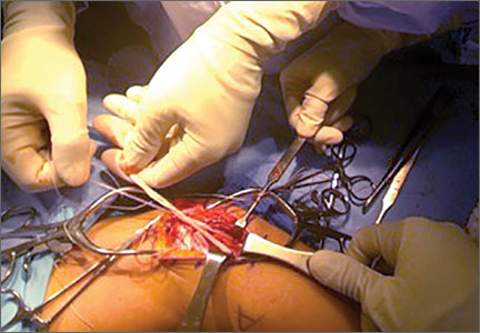
Extensor Pollicis Longus Ruptures in Distal Radius Fractures: Clinical and Cadaveric Studies With a New Therapeutic Intervention
Distal radius fractures are among the most common upper extremity injuries. A Swedish study noted that 75% of forearm fractures involve the distal radius.1 Extensor pollicis longus (EPL) ruptures are a well-documented complication (0.3% incidence2) of distal radius fractures.
The first description of EPL ruptures is attributed to Duplay in 1876 and was termed drummer boy’s palsy.3 Spontaneous EPL ruptures are often described in the setting of acute or chronic tenosynovitis.4,5 Beginning in the early 1930s, multiple case reports began to connect distal radius fractures with EPL ruptures.6 Although EPL ruptures are rare, their consequences are substantial and typically necessitate reconstructive procedures. Extensor indicis proprius (EIP)-to-EPL tendon transfer has become a common surgical treatment for this complication. Increasing our knowledge of several characteristics associated with this complication may help clinically in preventing EPL ruptures.
Multiple studies have indicated that EPL ruptures occur more often in nondisplaced fractures and often occur between 6 and 8 weeks after injury.2,5,7,8 Several factors are implicated in the etiology of EPL ruptures in distal radius fractures. The classic 1979 study by Engkvist and Lundborg9 showed that the EPL tendon has an area of poor vascularity around the Lister tubercle. Explorations of nondisplaced distal radius fractures have shown an intact extensor retinaculum that allows the tendon to continue to travel through an enclosed space.4,5,7 In the setting of distal radius fracture, hematoma may contribute to tendon ruptures secondary to increased pressure within an intact third dorsal compartment, which further compromises vascularity in this region of the EPL tendon.
Recognition and prevention of an impending EPL rupture may help avoid the significant consequences of this complication. Decompression and release of the third dorsal compartment have been described as constituting a prophylactic surgical option.10,11 Early thumb range of motion is also advocated to help prevent EPL rupture.9 However, results reported in the literature are inconclusive as to the effectiveness of these or indeed any preventive procedures. Dr. Lourie uses a novel technique that involves aspiration of the third dorsal compartment in patients with clinical symptoms associated with impending EPL rupture. Needle decompression, a less invasive option, can be quickly performed in an office, and it is hypothesized that removal of the hematoma may prevent EPL ruptures.
In the present study, we retrospectively reviewed Dr. Lourie’s records of patients with EPL ruptures in association with distal radius fractures to help delineate which radiographic and clinical characteristics identify patients at risk for these ruptures. A cadaveric model of a nondisplaced distal radius fracture was then created in order to simulate a change in third compartment pressures before and after needle decompression. We present preliminary outcomes on a case series of 4 patients who underwent aspiration of the third compartment and who were thought to be at risk for EPL rupture.
Materials and Methods
Institutional review board approval was obtained for this study. From Dr. Lourie’s records, 19 patients treated between 1998 and 2009 were identified as having confirmed or clinically impending EPL ruptures in association with nonoperative treatment of distal radius fractures. Prodromal symptoms that were used to diagnose impending EPL ruptures included pain with resisted active EPL extension, pain with passive flexion of the thumb interphalangeal joint, and localized swelling over the third dorsal compartment of the wrist.5,7,10,12 Eleven patients had complete radiographs, which were reviewed for radiographic characteristics. Posteroanterior (PA) and lateral radiographs of the injured wrist were reviewed. On the PA radiographs, fraction location was measured from the tip of the radial styloid using a line perpendicular to the radial shaft. Fractures were also evaluated for displacement and intra-articular involvement.
A cadaveric model was developed to evaluate compartment pressures in the EPL sheath in a simulated distal radius fracture. Six fresh-frozen cadaveric forearms were used after being thawed at room temperature. The cadavers were radiographically evaluated to determine that there was no evidence of prior fracture. A Stryker compartment pressure monitoring system (Stryker, Kalamazoo, Michigan) was used to take initial pressure readings in the third dorsal compartment slightly ulnar to the Lister tubercle (preinjection readings). A limited volar approach was then created. Under fluoroscopy, a half-inch osteotome was used to make an extra-articular fracture line in the distal radius, in the region of the Lister tubercle. The osteotomy was a mean of 1.2 cm from the distal aspect of the radius. The osteotomy site was then injected from the volar aspect with 5 mL of radiopaque (Hypaque) dye (Figure 1). Fluid extravasation into the third dorsal compartment was visualized under fluoroscopy (Figures 2–4). The monitor was then reinserted into the EPL sheath, and once again pressures were measured (postinjection readings). An 18-gauge needle was then used to aspirate the compartment just ulnar to the Lister tubercle. Compartment pressures were measured a final time (postaspiration readings). For all readings, 3 pressure measurements were recorded and then averaged. Pressure measurements were compared using t test.
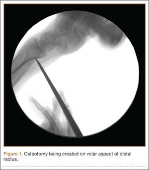
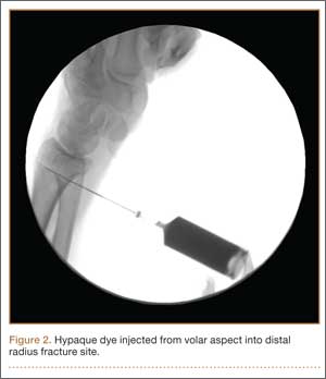
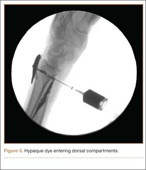
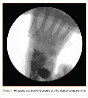
In the office, the third dorsal compartment was aspirated after skin preparation with povidone-iodine. The Lister tubercle is typically palpable along the dorsal distal radius and is aligned with the cleft between the index and long fingers. Aspiration with an 18-gauge needle is performed just ulnar to the Lister tubercle in the EPL sheath, and hematoma is evacuated. The patient is then placed back into a long-arm cast or splint per the clinical situation.
Results
Patient age ranged from 17 to 81 years. Eight (1 male, 7 female) patients sustained an EPL rupture a mean of 46 days after initial trauma (range, 21-118 days). Two patients were treated with a prophylactic EPL transposition secondary to clinically apparent impending rupture, and 4 were treated with prophylactic needle decompression of the third compartment. Ruptures were treated with EIP-to-EPL transfers.
As in other studies, each patient’s radiographs showed a nondisplaced fracture and a transverse fracture line. Six patients also had a longitudinal, intra-articular fracture line that exited in a common spot between the scaphoid and the lunate facet.
Results in our cadaveric model were consistent with those in in vitro decompression of the third dorsal compartment (Table 1). In the cadaver model, mean (SD) initial third dorsal compartment pressure was 0.77 (0.88) mm Hg. Mean (SD) pressure after osteotomy and Hypaque injection was 25.5 (11.11) mm Hg. After simulated therapeutic aspiration, mean (SD) pressure decreased to 1.61 (1.40) mm Hg. Mean change in pressure from after injection to after aspiration was 23.89 mm Hg (P = .000388) (Table 2).
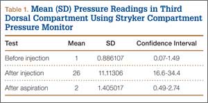
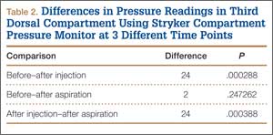
Information from other studies and from Dr. Lourie’s experience was used to identify patients at significant risk for EPL ruptures in association with distal radius fractures. Four patients in Dr. Lourie’s practice between 2004 and 2009 had characteristic findings, including a nondisplaced distal radius fracture, localized swelling over the third dorsal compartment, and pain with resisted active EPL extension. Prophylactic aspiration and hematoma evacuation were performed in this series, yielding a mean hematoma amount of 2 mL (Table 3).
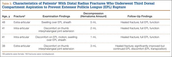
For all 4 patients, aspirations were performed within 2 weeks of injury. Subjectively, these patients described almost immediate pain relief and less discomfort with EPL motion after aspiration. Three of the 4 reported sustained pain relief on close follow-up 7 and 14 days after aspiration. The fourth patient continued to have pain over the third dorsal compartment, though she described it as significantly improved. Her initial fracture contained about 50% dorsal comminution, and she began to have a significant callus response. After 2 months of continued symptoms, and out of concern about consequences of an impending rupture, open decompression and transposition of the EPL were performed. In follow-up over 29 months, this patient continued to do well and had full EPL function. The 3 patients treated with aspiration alone have not had an EPL rupture (range of follow-up, 29-89 months).
Discussion
Distal radius fractures are very common injuries, and treating physicians must attempt to prevent possible complications. EPL tendon ruptures continue to be rare events (incidence, <1%) in association with distal radius fractures. Although statistics vary, studies have found a higher incidence in nondisplaced (vs displaced) distal radius fractures.5,7,10 Ruptures in nondisplaced fractures occur within 2 weeks to 3 years after injury but typically an average of 6 weeks after injury.2,4,7-9 Prodromal symptoms often include tenderness and swelling around the dorsal distal radius region around the Lister tubercle.7,11,12 Patients may complain of pain with active thumb extension or passive thumb range of motion.11 Rupture is indicated by an inability to actively extend the thumb.
Studies have shown that the tendon rupture site is around the Lister tubercle.7 No single cause for EPL ruptures has been confirmed, and the etiology is likely a mix of factors in relation to the clinical situation. Two theories have been espoused for the relation between EPL ruptures and distal radius fractures. The mechanical theory involves a prominent spicule of bone abrading the tendon and subsequently causing rupture.5,9 This seems less likely for nondisplaced fractures. The vascular theory centers on a watershed region of the EPL tendon around the Lister tubercle. Studies have found microangiographic evidence of a 5-mm portion of tendon around the Lister tubercle that has no mesotenon and poor vascularity.7,9 The tendon in this section may be reliant on synovial diffusion for nutrition,7 but hematoma may displace synovial fluid, interfering with tendon nutrition.
Researchers have studied the third dorsal compartment in patients with impending or established ruptures. In a series by Hirasawa and colleagues,7 11 patients with a nondisplaced fracture and a tendon rupture had an intact retinaculum and smooth bony surfaces on the dorsal radius. Periosteal hypertrophy and narrowing of the third compartment were noted. In another series, Helal and colleagues5 reported on 16 patients (nondisplaced and displaced fractures) who had possible EPL ruptures over a 4-year period. In all cases, the extensor retinaculum was intact. Likewise, the 7 patients with EPL ruptures in a series by Bonatz and colleagues4 had an intact extensor retinaculum. On exploration, Bunata10 noted fluid collections, including hematomas, within the sheath, as well as a lack of bony prominences. Simpson12 explored 2 cases of blunt trauma, no fracture, and subsequent EPL rupture. Clinically these 2 patients had swelling in the region of the Lister tubercle, and surgically they were found to have a distended, blood-filled sheath. These ruptures may correlate with nondisplaced distal radius fractures and provide further evidence supporting the vascular theory of ruptures. The combination of intact compartment and volume overload presents a situation akin to compartment syndrome. Acute compartment decompression with needle evacuation would theoretically relieve the vascular insult.
In the study by Helal and colleagues,5 Hypaque injections were given to patients with nondisplaced distal radius fractures. The dye remained in the third dorsal compartment, which implies an intact closed space. That study used a cadaveric model as well, with distal radius osteotomies performed to simulate a nondisplaced distal radius fracture. The authors noted an intact extensor retinaculum in their model. Our cadaver model is similar, except we measured pressures in the third compartment; our model indicated increased compartment pressures within the EPL sheath. Subsequent aspiration in our cadaveric study led to lower pressures in the third dorsal compartment. This cadaveric model implies that needle decompression of the third dorsal compartment may be beneficial in the setting of nondisplaced distal radius fractures and symptoms indicating a compromised EPL.
Splinting is an important factor that may help prevent EPL tendon ruptures after distal radius fractures. Synovial diffusion may be the primary mechanism for delivering nutrition to the EPL tendon.7 A splint that allows thumb metacarpophalangeal and interphalangeal flexion may provide the EPL motion needed for effective synovial nutritional pathways.9 Prodromal symptoms of tendon rupture should then be carefully monitored.
Conclusion
Results of our retrospective review are consistent with previous results elucidating the risk factors for EPL ruptures in association with distal radius fractures. In our patients who sustained EPL ruptures, findings included nondisplaced fractures, about 50% with an intra-articular component. Clinical findings included localized swelling over the third dorsal compartment, pain with resisted active EPL extension, and pain with passive flexion of the thumb interphalangeal joint. The cadaveric portion of this study indicated a significant change in pressure in the third dorsal compartment after aspiration. Preliminary outcomes in this 4-patient series are no EPL ruptures after prophylactic aspiration. Hematoma evacuation after nondisplaced distal radius fractures may become a useful addition to the surgeon’s armamentarium. Studies are needed to determine if needle aspiration of the third dorsal compartment can become an office-based procedure with value in preventing EPL ruptures in the appropriate clinical situation.
1. Alffram PA, Bauer GC. Epidemiology of fractures of the forearm. A biomechanical investigation of bone strength. J Bone Joint Surg Am. 1962;44:105-114.
2. Hove LM. Delayed rupture of the thumb extensor tendon. A 5-year study of 18 consecutive cases. Acta Orthop Scand. 1994;65(2):199-203.
3. Duplay. Rupture sous-cutanee du tendon du long extenseur du pouce, au niveau de la tabatiere anatomique. Bull Et Mem de la Soc de Chir de Paris. 1876.
4. Bonatz E, Kramer TD, Masear VR. Rupture of the extensor pollicis longus tendon. Am J Orthop. 1996;25(2):118-122.
5. Helal B, Chen SC, Iwegbu G. Rupture of the extensor pollicis longus tendon in undisplaced Colles’ type of fracture. Hand. 1982;14(1):41-47.
6. McMaster PE. Late ruptures of extensor and flexor pollicis longus tendons following Colles’ fracture. J Bone Joint Surg Am. 1932;14:93-101.
7. Hirasawa Y, Katsumi Y, Akiyoshi T, Tamai K, Tokioka T. Clinical and microangiographic studies on rupture of the E.P.L. tendon after distal radius fractures. J Hand Surg Br. 1990;15(1):51-57.
8. Björkman A, Jörgsholm P. Rupture of the extensor pollicis longus tendon: a study of aetiological factors. Scand J Plast Reconstruct Surg Hand Surg. 2004;38(1):32-35.
9. Engkvist O, Lundborg G. Rupture of the extensor pollicis longus tendon after fracture of the lower end of the radius—a clinical and microangiographic study. Hand. 1979;11(1):76-86.
10. Bunata RE. Impending rupture of the extensor pollicis longus tendon after a minimally displaced Colles fracture. A case report. J Bone Joint Surg Am. 1983;65(3):401-402.
11. Skoff HD. Postfracture extensor pollicis longus tenosynovitis and tendon rupture: a scientific study and personal series. Am J Orthop. 2003;32(5):245-247.
12. Simpson RG. Delayed rupture of extensor pollicis longus tendon following closed injury. Hand. 1977;9(2):160-161.
Distal radius fractures are among the most common upper extremity injuries. A Swedish study noted that 75% of forearm fractures involve the distal radius.1 Extensor pollicis longus (EPL) ruptures are a well-documented complication (0.3% incidence2) of distal radius fractures.
The first description of EPL ruptures is attributed to Duplay in 1876 and was termed drummer boy’s palsy.3 Spontaneous EPL ruptures are often described in the setting of acute or chronic tenosynovitis.4,5 Beginning in the early 1930s, multiple case reports began to connect distal radius fractures with EPL ruptures.6 Although EPL ruptures are rare, their consequences are substantial and typically necessitate reconstructive procedures. Extensor indicis proprius (EIP)-to-EPL tendon transfer has become a common surgical treatment for this complication. Increasing our knowledge of several characteristics associated with this complication may help clinically in preventing EPL ruptures.
Multiple studies have indicated that EPL ruptures occur more often in nondisplaced fractures and often occur between 6 and 8 weeks after injury.2,5,7,8 Several factors are implicated in the etiology of EPL ruptures in distal radius fractures. The classic 1979 study by Engkvist and Lundborg9 showed that the EPL tendon has an area of poor vascularity around the Lister tubercle. Explorations of nondisplaced distal radius fractures have shown an intact extensor retinaculum that allows the tendon to continue to travel through an enclosed space.4,5,7 In the setting of distal radius fracture, hematoma may contribute to tendon ruptures secondary to increased pressure within an intact third dorsal compartment, which further compromises vascularity in this region of the EPL tendon.
Recognition and prevention of an impending EPL rupture may help avoid the significant consequences of this complication. Decompression and release of the third dorsal compartment have been described as constituting a prophylactic surgical option.10,11 Early thumb range of motion is also advocated to help prevent EPL rupture.9 However, results reported in the literature are inconclusive as to the effectiveness of these or indeed any preventive procedures. Dr. Lourie uses a novel technique that involves aspiration of the third dorsal compartment in patients with clinical symptoms associated with impending EPL rupture. Needle decompression, a less invasive option, can be quickly performed in an office, and it is hypothesized that removal of the hematoma may prevent EPL ruptures.
In the present study, we retrospectively reviewed Dr. Lourie’s records of patients with EPL ruptures in association with distal radius fractures to help delineate which radiographic and clinical characteristics identify patients at risk for these ruptures. A cadaveric model of a nondisplaced distal radius fracture was then created in order to simulate a change in third compartment pressures before and after needle decompression. We present preliminary outcomes on a case series of 4 patients who underwent aspiration of the third compartment and who were thought to be at risk for EPL rupture.
Materials and Methods
Institutional review board approval was obtained for this study. From Dr. Lourie’s records, 19 patients treated between 1998 and 2009 were identified as having confirmed or clinically impending EPL ruptures in association with nonoperative treatment of distal radius fractures. Prodromal symptoms that were used to diagnose impending EPL ruptures included pain with resisted active EPL extension, pain with passive flexion of the thumb interphalangeal joint, and localized swelling over the third dorsal compartment of the wrist.5,7,10,12 Eleven patients had complete radiographs, which were reviewed for radiographic characteristics. Posteroanterior (PA) and lateral radiographs of the injured wrist were reviewed. On the PA radiographs, fraction location was measured from the tip of the radial styloid using a line perpendicular to the radial shaft. Fractures were also evaluated for displacement and intra-articular involvement.
A cadaveric model was developed to evaluate compartment pressures in the EPL sheath in a simulated distal radius fracture. Six fresh-frozen cadaveric forearms were used after being thawed at room temperature. The cadavers were radiographically evaluated to determine that there was no evidence of prior fracture. A Stryker compartment pressure monitoring system (Stryker, Kalamazoo, Michigan) was used to take initial pressure readings in the third dorsal compartment slightly ulnar to the Lister tubercle (preinjection readings). A limited volar approach was then created. Under fluoroscopy, a half-inch osteotome was used to make an extra-articular fracture line in the distal radius, in the region of the Lister tubercle. The osteotomy was a mean of 1.2 cm from the distal aspect of the radius. The osteotomy site was then injected from the volar aspect with 5 mL of radiopaque (Hypaque) dye (Figure 1). Fluid extravasation into the third dorsal compartment was visualized under fluoroscopy (Figures 2–4). The monitor was then reinserted into the EPL sheath, and once again pressures were measured (postinjection readings). An 18-gauge needle was then used to aspirate the compartment just ulnar to the Lister tubercle. Compartment pressures were measured a final time (postaspiration readings). For all readings, 3 pressure measurements were recorded and then averaged. Pressure measurements were compared using t test.
In the office, the third dorsal compartment was aspirated after skin preparation with povidone-iodine. The Lister tubercle is typically palpable along the dorsal distal radius and is aligned with the cleft between the index and long fingers. Aspiration with an 18-gauge needle is performed just ulnar to the Lister tubercle in the EPL sheath, and hematoma is evacuated. The patient is then placed back into a long-arm cast or splint per the clinical situation.
Results
Patient age ranged from 17 to 81 years. Eight (1 male, 7 female) patients sustained an EPL rupture a mean of 46 days after initial trauma (range, 21-118 days). Two patients were treated with a prophylactic EPL transposition secondary to clinically apparent impending rupture, and 4 were treated with prophylactic needle decompression of the third compartment. Ruptures were treated with EIP-to-EPL transfers.
As in other studies, each patient’s radiographs showed a nondisplaced fracture and a transverse fracture line. Six patients also had a longitudinal, intra-articular fracture line that exited in a common spot between the scaphoid and the lunate facet.
Results in our cadaveric model were consistent with those in in vitro decompression of the third dorsal compartment (Table 1). In the cadaver model, mean (SD) initial third dorsal compartment pressure was 0.77 (0.88) mm Hg. Mean (SD) pressure after osteotomy and Hypaque injection was 25.5 (11.11) mm Hg. After simulated therapeutic aspiration, mean (SD) pressure decreased to 1.61 (1.40) mm Hg. Mean change in pressure from after injection to after aspiration was 23.89 mm Hg (P = .000388) (Table 2).
Information from other studies and from Dr. Lourie’s experience was used to identify patients at significant risk for EPL ruptures in association with distal radius fractures. Four patients in Dr. Lourie’s practice between 2004 and 2009 had characteristic findings, including a nondisplaced distal radius fracture, localized swelling over the third dorsal compartment, and pain with resisted active EPL extension. Prophylactic aspiration and hematoma evacuation were performed in this series, yielding a mean hematoma amount of 2 mL (Table 3).
For all 4 patients, aspirations were performed within 2 weeks of injury. Subjectively, these patients described almost immediate pain relief and less discomfort with EPL motion after aspiration. Three of the 4 reported sustained pain relief on close follow-up 7 and 14 days after aspiration. The fourth patient continued to have pain over the third dorsal compartment, though she described it as significantly improved. Her initial fracture contained about 50% dorsal comminution, and she began to have a significant callus response. After 2 months of continued symptoms, and out of concern about consequences of an impending rupture, open decompression and transposition of the EPL were performed. In follow-up over 29 months, this patient continued to do well and had full EPL function. The 3 patients treated with aspiration alone have not had an EPL rupture (range of follow-up, 29-89 months).
Discussion
Distal radius fractures are very common injuries, and treating physicians must attempt to prevent possible complications. EPL tendon ruptures continue to be rare events (incidence, <1%) in association with distal radius fractures. Although statistics vary, studies have found a higher incidence in nondisplaced (vs displaced) distal radius fractures.5,7,10 Ruptures in nondisplaced fractures occur within 2 weeks to 3 years after injury but typically an average of 6 weeks after injury.2,4,7-9 Prodromal symptoms often include tenderness and swelling around the dorsal distal radius region around the Lister tubercle.7,11,12 Patients may complain of pain with active thumb extension or passive thumb range of motion.11 Rupture is indicated by an inability to actively extend the thumb.
Studies have shown that the tendon rupture site is around the Lister tubercle.7 No single cause for EPL ruptures has been confirmed, and the etiology is likely a mix of factors in relation to the clinical situation. Two theories have been espoused for the relation between EPL ruptures and distal radius fractures. The mechanical theory involves a prominent spicule of bone abrading the tendon and subsequently causing rupture.5,9 This seems less likely for nondisplaced fractures. The vascular theory centers on a watershed region of the EPL tendon around the Lister tubercle. Studies have found microangiographic evidence of a 5-mm portion of tendon around the Lister tubercle that has no mesotenon and poor vascularity.7,9 The tendon in this section may be reliant on synovial diffusion for nutrition,7 but hematoma may displace synovial fluid, interfering with tendon nutrition.
Researchers have studied the third dorsal compartment in patients with impending or established ruptures. In a series by Hirasawa and colleagues,7 11 patients with a nondisplaced fracture and a tendon rupture had an intact retinaculum and smooth bony surfaces on the dorsal radius. Periosteal hypertrophy and narrowing of the third compartment were noted. In another series, Helal and colleagues5 reported on 16 patients (nondisplaced and displaced fractures) who had possible EPL ruptures over a 4-year period. In all cases, the extensor retinaculum was intact. Likewise, the 7 patients with EPL ruptures in a series by Bonatz and colleagues4 had an intact extensor retinaculum. On exploration, Bunata10 noted fluid collections, including hematomas, within the sheath, as well as a lack of bony prominences. Simpson12 explored 2 cases of blunt trauma, no fracture, and subsequent EPL rupture. Clinically these 2 patients had swelling in the region of the Lister tubercle, and surgically they were found to have a distended, blood-filled sheath. These ruptures may correlate with nondisplaced distal radius fractures and provide further evidence supporting the vascular theory of ruptures. The combination of intact compartment and volume overload presents a situation akin to compartment syndrome. Acute compartment decompression with needle evacuation would theoretically relieve the vascular insult.
In the study by Helal and colleagues,5 Hypaque injections were given to patients with nondisplaced distal radius fractures. The dye remained in the third dorsal compartment, which implies an intact closed space. That study used a cadaveric model as well, with distal radius osteotomies performed to simulate a nondisplaced distal radius fracture. The authors noted an intact extensor retinaculum in their model. Our cadaver model is similar, except we measured pressures in the third compartment; our model indicated increased compartment pressures within the EPL sheath. Subsequent aspiration in our cadaveric study led to lower pressures in the third dorsal compartment. This cadaveric model implies that needle decompression of the third dorsal compartment may be beneficial in the setting of nondisplaced distal radius fractures and symptoms indicating a compromised EPL.
Splinting is an important factor that may help prevent EPL tendon ruptures after distal radius fractures. Synovial diffusion may be the primary mechanism for delivering nutrition to the EPL tendon.7 A splint that allows thumb metacarpophalangeal and interphalangeal flexion may provide the EPL motion needed for effective synovial nutritional pathways.9 Prodromal symptoms of tendon rupture should then be carefully monitored.
Conclusion
Results of our retrospective review are consistent with previous results elucidating the risk factors for EPL ruptures in association with distal radius fractures. In our patients who sustained EPL ruptures, findings included nondisplaced fractures, about 50% with an intra-articular component. Clinical findings included localized swelling over the third dorsal compartment, pain with resisted active EPL extension, and pain with passive flexion of the thumb interphalangeal joint. The cadaveric portion of this study indicated a significant change in pressure in the third dorsal compartment after aspiration. Preliminary outcomes in this 4-patient series are no EPL ruptures after prophylactic aspiration. Hematoma evacuation after nondisplaced distal radius fractures may become a useful addition to the surgeon’s armamentarium. Studies are needed to determine if needle aspiration of the third dorsal compartment can become an office-based procedure with value in preventing EPL ruptures in the appropriate clinical situation.
1. Alffram PA, Bauer GC. Epidemiology of fractures of the forearm. A biomechanical investigation of bone strength. J Bone Joint Surg Am. 1962;44:105-114.
2. Hove LM. Delayed rupture of the thumb extensor tendon. A 5-year study of 18 consecutive cases. Acta Orthop Scand. 1994;65(2):199-203.
3. Duplay. Rupture sous-cutanee du tendon du long extenseur du pouce, au niveau de la tabatiere anatomique. Bull Et Mem de la Soc de Chir de Paris. 1876.
4. Bonatz E, Kramer TD, Masear VR. Rupture of the extensor pollicis longus tendon. Am J Orthop. 1996;25(2):118-122.
5. Helal B, Chen SC, Iwegbu G. Rupture of the extensor pollicis longus tendon in undisplaced Colles’ type of fracture. Hand. 1982;14(1):41-47.
6. McMaster PE. Late ruptures of extensor and flexor pollicis longus tendons following Colles’ fracture. J Bone Joint Surg Am. 1932;14:93-101.
7. Hirasawa Y, Katsumi Y, Akiyoshi T, Tamai K, Tokioka T. Clinical and microangiographic studies on rupture of the E.P.L. tendon after distal radius fractures. J Hand Surg Br. 1990;15(1):51-57.
8. Björkman A, Jörgsholm P. Rupture of the extensor pollicis longus tendon: a study of aetiological factors. Scand J Plast Reconstruct Surg Hand Surg. 2004;38(1):32-35.
9. Engkvist O, Lundborg G. Rupture of the extensor pollicis longus tendon after fracture of the lower end of the radius—a clinical and microangiographic study. Hand. 1979;11(1):76-86.
10. Bunata RE. Impending rupture of the extensor pollicis longus tendon after a minimally displaced Colles fracture. A case report. J Bone Joint Surg Am. 1983;65(3):401-402.
11. Skoff HD. Postfracture extensor pollicis longus tenosynovitis and tendon rupture: a scientific study and personal series. Am J Orthop. 2003;32(5):245-247.
12. Simpson RG. Delayed rupture of extensor pollicis longus tendon following closed injury. Hand. 1977;9(2):160-161.