User login
Graft Choice in ACL Reconstruction May Affect Revision Rates
ORLANDO, FL—Using soft tissue allografts for anterior cruciate ligament (ACL) reconstructions may increase the risks for a revision reconstruction postoperatively, according to research presented at the American Orthopedic Society for Sports Medicine’s Specialty Day.
Researchers analyzed data from the Kaiser Permanente ACLR Registry. Of the cases analyzed, 4,557 involved bone-patellar tendon-bone (BPTB) autografts, 3,751 soft tissue allograft, and 5,707 hamstring allograft.
After a 3-year follow-up, the overall revision rates were 2.5% for BPTB autographs, 3.5% for hamstring autografts, and 3.7% for soft tissue allografts. Non-processed soft tissue allografts were not found to have a statistically significantly different risk of revision compared to BPTB autografts. However, compared to BPTB autografts, allografts processed with more than 1.8Mrads irradiation had a more than 2 times higher risk of revision, and grafts processed with more than 1.8Mrads or high pressure chemical processing had a more than 4 to 6 times higher risk of revision. This was true even after adjustments for age, gender, and race.
Management of the Biconcave (B2) Glenoid in Shoulder Arthroplasty: Technical Considerations
Total shoulder arthroplasty (TSA) has demonstrated excellent long-term clinical outcomes for the treatment of advanced glenohumeral osteoarthritis (OA).1-5 Glenohumeral OA is characterized by a broad spectrum of glenoid pathology. Both the morphology of the glenoid and humeral head subluxation are important preoperative factors to evaluate, as these have been shown to adversely impact shoulder arthroplasty outcomes.6,7
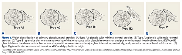
Walch and colleagues8 have previously classified glenoid morphology in cases of advanced glenohumeral arthritis based on the preoperative computed tomography (CT) scans of individuals undergoing shoulder arthroplasty (Figures 1A-1E). The biconcave (B2) glenoid is characterized by asymmetric posterior bone loss and a posterior translated humeral head that is seated in a biconcave glenoid. The degree and extent of bone loss in the B2 glenoid can be highly variable, ranging from the classic interpretation, in which 50% of the native glenoid fossa is preserved, to the more extreme case with little remaining native anterior glenoid. Scalise and colleagues9 have reported that determining the premorbid native glenoid version with a 3-dimensional (3D) glenoid vault model can aid in differentiating a pathologic B2 glenoid from a nonpathologic type C glenoid.
The B2 glenoid in particular has been associated with poor shoulder arthroplasty outcomes and component survivorship.6,10-12 There are many factors that are thought to contribute to this problem, such as glenoid component malposition, or undercorrection of the pathologic retroversion.6,13,14 Walch and colleagues10 reported that if the neoglenoid retroversion was greater than 27°, there was a 44% incidence of loosening and/or instability and 60% of the dislocations were observed when the humeral head subluxation was greater than 80%. Cases with severe posterior glenoid bone deficiency present a unique challenge to the surgeon, and the ability to accurately and securely place an implant in the correct anatomic position can be compromised. Standard TSA has proven excellent outcomes in the setting of typical glenohumeral OA, but in the B2 glenoid with significant posterior bone erosion, additional attention must be given to ensure adequate correction of the bony deformity, soft tissue balancing, and implant stability.
Several strategies that have been proposed to address extreme bone loss in the B2 glenoid will be discussed in this review. These include hemiarthroplasty, TSA with asymmetric reaming of the high side, TSA with bone grafting of the posterior glenoid bone loss, TSA with an augmented glenoid component, and reverse shoulder arthroplasty (RSA). Importantly, while these techniques have been proposed for managing the B2 glenoid, currently there is no gold standard consensus for the treatment of this condition. The purpose of this review is to highlight important characteristics of the B2 glenoid morphology on clinical outcomes and discuss the current surgical management options for this condition.
Preoperative Planning
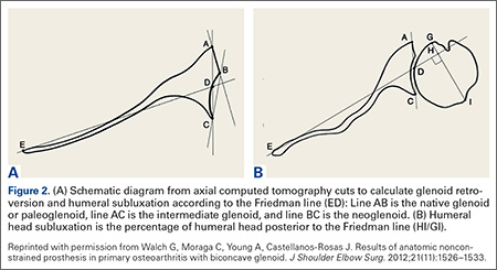
Being able to accurately determine the amount of retroversion is critical for preoperative planning. Friedman and colleagues15 initially described a method to measure glenoid retroversion; however, this is less accurate in B2 glenoids (Figures 2A, 2B). More recently, Rouleau and colleagues16 have validated and published methods to measure glenoid retroversion and subluxation in the B2 glenoid using 3 reference lines: the paleoglenoid (native glenoid surface), intermediate glenoid (line from anterior and posterior edge), and neoglenoid (eroded posterior surface) (Figure 2).
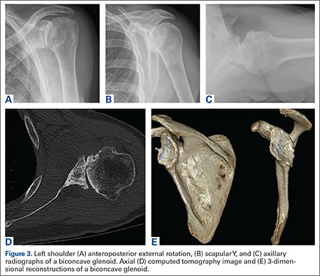
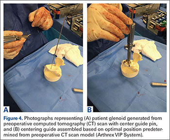
Preoperative evaluation starts with plain radiographs; however, additional imaging is needed, as the axillary view has shown to overestimate retroversion in 86% of patients (Figures 3A-3E).17 For a detailed evaluation of the glenoid retroversion and bone deficiency, CT scans with 3D reconstructions are useful.18,19 The surgical plan should be guided by the location and extent of glenoid bone loss. One tool that has been developed to help in predicting premorbid glenoid version, inclination, and position of the joint line is the 3D virtual glenoid vault model.9,20,21 This helps determine accurate premorbid glenoid anatomy and has been shown to assist in the selection of the optimal implant in an attempt to restore native glenoid anatomy, and avoid peg perforation.21 Patient-specific instrumentation (PSI) for shoulder arthroplasty is being used more frequently and has shown promise for more accurate glenoid component placement, particularly in the complex glenoid with severe bone deficiency. PSI involves creating a custom-fitted guide that is referenced to surface anatomy derived from the preoperative CT scan, which can then direct the surgeon toward optimal implant position with regard to glenoid component location, version and inclination (Figures 4A, 4B). Early reports show that PSI has resulted in a significant reduction in the frequency of malpositioned glenoid implants, with the greatest benefit observed in patients with retroversion in excess of 16°.22
Surgical Management
Hemiarthroplasty
Shoulder hemiarthroplasty has been traditionally described as an option for younger, more active patients in whom longevity of the glenoid component is a concern, or in patients with inadequate glenoid bone stock to tolerate a glenoid component. While there are no reports of hemiarthroplasty specifically for patients with B2 glenoids, one study has examined the effect of glenoid morphology on the outcomes of hemiarthroplasty for shoulder osteoarthritis. Levine and colleagues7 reported inferior clinical outcomes after shoulder hemiarthroplasty in patients with eccentric posterior glenoid wear. Several authors have advocated a “ream-and-run” technique to create a concentric glenoid and re-center the humeral head while still maintaining the native glenoid.23,24 However, in a recent series of 162 ream-and-run procedures, Gilmer and colleagues25 reported that only 23% of patients with B2 glenoid geometry achieved a minimal clinically important change in patient-reported outcome scores and 14% required revision. Furthermore, Lynch and colleagues26 found that progressive medial erosion and recurrent posterior glenoid erosion occur in a significant percentage of patients at early follow-up. Given these recent findings, the use of hemiarthroplasty alone or a ream-and-run procedure for patients with B2 glenoid morphology should be approached with caution.
Total Shoulder Arthroplasty
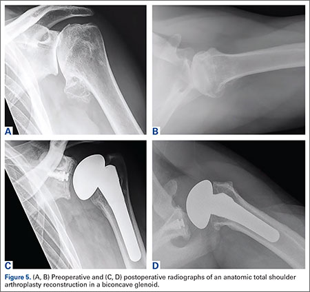
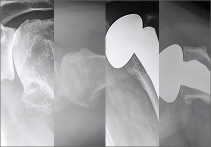
As with any TSA, the primary goals in treating patients with B2 glenoid defects are to provide the patient with a pain-free, stable, and functional shoulder (Figures 5A-5D). There are, however, a few challenges that are unique to TSA in the setting of B2 glenoid defects. Because the humeral head is often subluxated posteriorly into the defect, the anterior capsule and rotator cuff can tighten while the posterior aspect of the joint becomes lax. These soft tissues must be balanced during TSA in order to stabilize the shoulder and restore the appropriate length-tension relationship of the rotator cuff. The other primary concern is restoration of appropriate glenoid version and lateralization. To accomplish this, the most common techniques utilized are asymmetric reaming, bone graft augmentation, and glenoid component augmentation.27,28
Asymmetric Reaming. One of the more readily utilized techniques for addressing the B2 glenoid during TSA is eccentric or asymmetric reaming. During this process, the anterior glenoid is preferentially reamed while little to no bone is removed posteriorly. This technique is generally felt to be sufficient to treat posterior defects up to 5 mm to 8 mm or retroversion up to 15°.28 These upper limits have been confirmed in a number of cadaveric and simulated models.29-31
The success of this technique hinges on excellent glenoid exposure. With appropriate retractors in place, the anterior capsulolabral complex, including the biceps insertion, is resected to improve visualization. The inferior capsule must be resected carefully to ensure exposure and better motion postoperatively. On the other hand, it is imperative to protect the posterior capsulolabral attachments because of the increased risk of posterior instability in patients with B2 glenoids.
Detailed imaging such as CT scans with 3D reconstructions have improved our understanding of the degree of the deformities in all directions, which can better guide the reaming. PSI and planning software developed to improve the surgeon’s ability to place the glenoid component centrally in the best possible position after version correction can be even more helpful. We find that using a burr to provisionally lower the high side (anterior) provides a more en face view, which subsequently makes the eccentric reaming easier. As a guide, we will not ream more than 1 cm of anterior bone or attempt to correct more than ~20° of retroversion. The goal should be to create a glenoid surface that is more neutral and congruent to the posterior surface of the glenoid component while not overmedializing the component.
Although eccentric reaming may be one of the more straightforward methods for addressing posterior glenoid erosion, it is not without a number of potential downsides. When attempting to correct defects >10 mm or retroversion beyond 15°, excessive medialization of the implant can occur. Although increasing the thickness of the glenoid component can compensate for small amounts of medialization, excessive medialization can lead to a number of issues.27,28,32 As reaming progresses medially, the risk of keel penetration increases as the glenoid vault narrows.30,32 Further medialization decreases posterior cortical support for the implant, which increases the risk of component loosening and subsidence.33-35 The more medial the implant is placed, the smaller the surface of available bone for implant fixation. This often requires utilization of a smaller sized glenoid component that may result in component mismatch with the humeral implant. Finally, excessive medialization has the potential to under tension the rotator cuff, leading to decreased shoulder stability, strength, and function.
Bone Graft Augmentation. When posterior erosion becomes too excessive to address with eccentric reaming alone, defect augmentation is another option to consider (Figures 6A-6E). While technically more demanding, bone graft also provides the advantage of better re-creating the natural joint line and center of rotation of the glenohumeral joint.
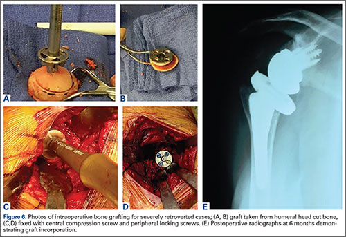
For most defects, the resected humeral head provides the ideal source of graft. After initial reaming of the anterior glenoid, the defect must be sized and measured. We then recommend using a guided, cannulated system to place a central pin, lying perpendicular to the glenoid axis in neutral position. The anterior glenoid is then reamed enough to create a flat surface on which to attach the bone graft. The posterior surface is then gently burred to create a bleeding surface to enhance graft incorporation. The graft is then contoured to the defect and placed flush with the anterior glenoid. Cannulated screws are placed over guidewires to fix the graft. Using an arthroscopic cannula inserted posteriorly allows for easier placement of the guidewires and easier implantation of the screws. Although a reamer or burr can be used to contour the graft once it is fixed in place, this should be minimized to prevent loss of fixation. When the graft is fixed, we then cement the glenoid component into place.
Although good clinical results have been obtained with this technique, there is concern of incomplete graft healing and component loosening in the long term. Even in clinically asymptomatic and well functioning patients, some degree of radiographic lucency may be present in over 50% of cases.31,36,37 Glenoid Component Augmentation. To address the issues related to lucency and nonunion of bone graft augmentation, several augmented glenoid components have been developed. Augmented glenoid components have the benefit of filling posterior defects and stabilizing the shoulder without requiring excessive medialization (as often occurs with eccentric reaming) or union of a bone-to-bone interface (as is required in bone graft augmentation).38 Although many of the metal back designs experienced undesirably high failure rates and have since been recalled,39 more modern all-polyethylene components hold promise. The 2 most commonly utilized designs are the posterior step augment (DePuy) and the posterior wedge (Exactech). Although biomechanical analyses of both designs have demonstrated increased stability during loading in cadaveric and simulation models, the step augment (DePuy) has demonstrated increased stability and resistance to loosening.40,41 Although midterm results are not yet available for this newest generation of augmented components, short-term results with 2 to 3 years of follow-up have demonstrated excellent clinical outcomes.28
Reverse Total Shoulder Arthroplasty
While most commonly indicated for patients with rotator cuff tear arthropathy, RSA has recently been advocated for older patients with osteoarthritis and B2 glenoids in the setting of an intact rotator cuff. The semi-constrained design of the RSA is a potential solution to the static posterior humeral head subluxation seen in patients with B2 glenoid geometry (Figure 6E).
Technically, RSA is often an easier solution than a TSA with bone grafting because there is usually enough glenoid bone stock for fixation. That said, we always get a CT scan with 3D reconstructions to better appreciate the anatomy. Note that in B2 glenoids, the bone loss is typically posterior and inferior. RSA in the setting of a B2 glenoid is one of the ideal indications to use PSI to ensure ideal placement of the central pin, which is the key to glenoid baseplate positioning. Even when using a RSA, eccentric reaming and/or bone grafting allow for more ideal component placement. Using the same eccentric reaming techniques described above, one should try to ream to place the baseplate at 10° of retroversion. In cases where retroversion cannot be corrected to 10°, graft can be taken from the humeral head, iliac crest, or allograft. A benefit to using bone graft with RSA as opposed to TSA is that the graft can be fashioned to the baseplate, impacted/compressed into the B2 glenoid, and then secured with a central compression screw and peripheral locking screws.
Mizuno and colleagues41 reported a retrospective series of 27 RSAs performed for primary glenohumeral osteoarthritis and biconcave glenoid. At a mean follow-up of nearly 5 years, the authors noted significant improvement in Constant scores and shoulder motion with minimal complications. There was no recurrence of posterior instability observed by the time of final follow-up.41
RSA is a promising treatment for primary glenohumeral arthritis with posterior glenoid bone loss and static posterior subluxation in elderly or less active patients, but the longevity of these implants has yet to be established for younger, more active patients and requires further study.
Conclusion
Reconstruction of the B2 glenoid presents a challenging clinical problem that has been associated with poor clinical outcomes and implant survivorship. The high failure rate from glenoid component loosening and subsequent premature implant failure can be substantially decreased with accurate glenoid component positioning and appropriate correction of the pathologic glenoid retroversion. Careful preoperative planning is essential for accurate preparation and execution of the optimal surgical plan. There are many surgical strategies to address the B2 glenoid, but no consensus on the optimal method exists, as the technique should be uniquely customized to the individual’s pathology and surgeon preference (Table). Cases with mild deformity may be corrected with eccentric reaming and TSA, while the more severe deformities may require posterior glenoid bone grafting and/or augmented implants to restore native version. Finally, the RSA is a reliable option to restore stability and address bone deficiency for the severe B2 glenoid in an older, lower demand patient.
1. Barrett WP, Franklin JL, Jackins SE, Wyss CR, Matsen FA 3rd. Total shoulder arthroplasty. J Bone Joint Surg Am. 1987;69(6):865-872.
2. Bryant D, Litchfield R, Sandow M, Gartsman GM, Guyatt G, Kirkley A. A comparison of pain, strength, range of motion, and functional outcomes after hemiarthroplasty and total shoulder arthroplasty in patients with osteoarthritis of the shoulder. A systematic review and meta-analysis. J Bone Joint Surg Am. 2005;87(9):1947-1956.
3. Matsen FA 3rd. Early effectiveness of shoulder arthroplasty for patients who have primary glenohumeral degenerative joint disease. J Bone Joint Surg Am. 1996;78(2):260-264.
4. Fenlin JM Jr, Frieman BG. Indications, technique, and results of total shoulder arthroplasty in osteoarthritis. Orthop Clin North Am. 1998;29(3):423-434.
5. Singh JA, Sperling JW, Cofield RH. Revision surgery following total shoulder arthroplasty: Analysis of 2588 shoulders over three decades (1976 to 2008). J Bone Joint Surg Br. 2011;93(11):1513-1517.
6. Iannotti JP, Norris TR. Influence of preoperative factors on outcome of shoulder arthroplasty for glenohumeral osteoarthritis. J Bone Joint Surg Am. 2003;85-A(2):251-258.
7. Levine WN, Djurasovic M, Glasson JM, Pollock RG, Flatow EL, Bigliani LU. Hemiarthroplasty for glenohumeral osteoarthritis: Results correlated to degree of glenoid wear. J Shoulder Elbow Surg. 1997;6(5):449-454.
8. Walch G, Badet R, Boulahia A, Khoury A. Morphologic study of the glenoid in primary glenohumeral osteoarthritis. J Arthroplasty. 1999;14(6):756-760.
9. Scalise JJ, Codsi MJ, Bryan J, Iannotti JP. The three-dimensional glenoid vault model can estimate normal glenoid version in osteoarthritis. J Shoulder Elbow Surg. 2008;17(3):487-491.
10. Walch G, Moraga C, Young A, Castellanos-Rosas J. Results of anatomic nonconstrained prosthesis in primary osteoarthritis with biconcave glenoid. J Shoulder Elbow Surg. 2012;21(11):1526-1533.
11. Kany J, Katz D. How to deal with glenoid type B2 or C? How to prevent mistakes in implantation of glenoid component? Eur J Orthop Surg Traumatol. 2013;23(4):379-385.
12. Denard PJ, Walch G. Current concepts in the surgical management of primary glenohumeral arthritis with a biconcave glenoid. J Shoulder Elbow Surg. 2013;22(11):1589-1598.
13. Iannotti JP, Greeson C, Downing D, Sabesan V, Bryan JA. Effect of glenoid deformity on glenoid component placement in primary shoulder arthroplasty. J Shoulder Elbow Surg. 2012;21(1):48-55.
14. Ho JC, Sabesan VJ, Iannotti JP. Glenoid component retroversion is associated with osteolysis. J Bone Joint Surg Am. 2013;95(12):e82.
15. Friedman RJ, Hawthorne KB, Genez BM. The use of computerized tomography in the measurement of glenoid version. J Bone Joint Surg Am. 1992;74(7):1032-1037.
16. Rouleau DM, Kidder JF, Pons-Villanueva J, Dynamidis S, Defranco M, Walch G. Glenoid version: How to measure it? Validity of different methods in two-dimensional computed tomography scans. J Shoulder Elbow Surg. 2010;19(8):1230-1237.
17. Nyffeler RW, Jost B, Pfirrmann CW, Gerber C. Measurement of glenoid version: Conventional radiographs versus computed tomography scans. J Shoulder Elbow Surg. 2003;12(5):493-496.
18. Budge MD, Lewis GS, Schaefer E, Coquia S, Flemming DJ, Armstrong AD. Comparison of standard two-dimensional and three-dimensional corrected glenoid version measurements. J Shoulder Elbow Surg. 2011;20(4):577-583.
19. Bokor DJ, O’Sullivan MD, Hazan GJ. Variability of measurement of glenoid version on computed tomography scan. J Shoulder Elbow Surg. 1999;8(6):595-598.
20. Ganapathi A, McCarron JA, Chen X, Iannotti JP. Predicting normal glenoid version from the pathologic scapula: A comparison of 4 methods in 2- and 3-dimensional models. J Shoulder Elbow Surg. 2011;20(2):234-244.
21. Ricchetti ET, Hendel MD, Collins DN, Iannotti JP. Is premorbid glenoid anatomy altered in patients with glenohumeral osteoarthritis? Clin Orthop Relat Res. 2013;471(9):2932-2939.
22. Hendel MD, Bryan JA, Barsoum WK, et al. Comparison of patient-specific instruments with standard surgical instruments in determining glenoid component position: A randomized prospective clinical trial. J Bone Joint Surg Am. 2012;94(23):2167-2175.
23. Matsen FA 3rd, Warme WJ, Jackins SE. Can the ream and run procedure improve glenohumeral relationships and function for shoulders with the arthritic triad? Clin Orthop Relat Res. 2015;473(6):2088-2096.
24. Saltzman MD, Chamberlain AM, Mercer DM, Warme WJ, Bertelsen AL, Matsen FA 3rd. Shoulder hemiarthroplasty with concentric glenoid reaming in patients 55 years old or less. J Shoulder Elbow Surg. 2011;20(4):609-615.
25. Gilmer BB, Comstock BA, Jette JL, Warme WJ, Jackins SE, Matsen FA. The prognosis for improvement in comfort and function after the ream-and-run arthroplasty for glenohumeral arthritis: An analysis of 176 consecutive cases. J Bone Joint Surg Am. 2012;94(14):e102.
26. Lynch JR, Franta AK, Montgomery WH Jr, Lenters TR, Mounce D, Matsen FA 3rd. Self-assessed outcome at two to four years after shoulder hemiarthroplasty with concentric glenoid reaming. J Bone Joint Surg Am. 2007;89(6):1284-1292.
27. Donohue KW, Ricchetti ET, Iannotti JP. Surgical management of the biconcave (B2) glenoid. Curr Rev Musculoskelet Med. 2016;9(1):30-39.
28. Clavert P, Millett PJ, Warner JJ. Glenoid resurfacing: What are the limits to asymmetric reaming for posterior erosion? J Shoulder Elbow Surg. 2007;16(6):843-848.
29. Gillespie R, Lyons R, Lazarus M. Eccentric reaming in total shoulder arthroplasty: A cadaveric study. Orthopedics. 2009;32(1):21.
30. Neer CS 2nd, Morrison DS. Glenoid bone-grafting in total shoulder arthroplasty. J Bone Joint Surg Am. 1988;70(8):1154-1162.
31. Nowak DD, Bahu MJ, Gardner TR, et al. Simulation of surgical glenoid resurfacing using three-dimensional computed tomography of the arthritic glenohumeral joint: The amount of glenoid retroversion that can be corrected. J Shoulder Elbow Surg. 2009;18(5):680-688.
32. Strauss EJ, Roche C, Flurin PH, Wright T, Zuckerman JD. The glenoid in shoulder arthroplasty. J Shoulder Elbow Surg. 2009;18(5):819-833.
33. Walch G, Young AA, Boileau P, Loew M, Gazielly D, Mole D. Patterns of loosening of polyethylene keeled glenoid components after shoulder arthroplasty for primary osteoarthritis: Results of a multicenter study with more than five years of follow-up. J Bone Joint Surg Am. 2012;94(2):145-150.
34. Walch G, Young AA, Melis B, Gazielly D, Loew M, Boileau P. Results of a convex-back cemented keeled glenoid component in primary osteoarthritis: Multicenter study with a follow-up greater than 5 years. J Shoulder Elbow Surg. 2011;20(3):385-394.
35. Klika BJ, Wooten CW, Sperling JW, et al. Structural bone grafting for glenoid deficiency in primary total shoulder arthroplasty. J Shoulder Elbow Surg. 2014;23(7):1066-1072.
36. Sabesan V, Callanan M, Sharma V, Iannotti JP. Correction of acquired glenoid bone loss in osteoarthritis with a standard versus an augmented glenoid component. J Shoulder Elbow Surg. 2014;23(7):964-973.
37. Steinmann SP, Cofield RH. Bone grafting for glenoid deficiency in total shoulder replacement. J Shoulder Elbow Surg. 2000;9(5):361-367.
38. Cil A, Sperling JW, Cofield RH. Nonstandard glenoid components for bone deficiencies in shoulder arthroplasty. J Shoulder Elbow Surg. 2014;23(7):e149-e157.
39. Iannotti JP, Lappin KE, Klotz CL, Reber EW, Swope SW. Liftoff resistance of augmented glenoid components during cyclic fatigue loading in the posterior-superior direction. J Shoulder Elbow Surg. 2013;22(11):1530-1536.
40. Knowles NK, Ferreira LM, Athwal GS. Augmented glenoid component designs for type B2 erosions: A computational comparison by volume of bone removal and quality of remaining bone. J Shoulder Elbow Surg. 2015;24(8):1218-1226.
41. Mizuno N, Denard PJ, Raiss P, Walch G. Reverse total shoulder arthroplasty for primary glenohumeral osteoarthritis in patients with a biconcave glenoid. J Bone Joint Surg Am. 2013;95(14):1297-1304.
Total shoulder arthroplasty (TSA) has demonstrated excellent long-term clinical outcomes for the treatment of advanced glenohumeral osteoarthritis (OA).1-5 Glenohumeral OA is characterized by a broad spectrum of glenoid pathology. Both the morphology of the glenoid and humeral head subluxation are important preoperative factors to evaluate, as these have been shown to adversely impact shoulder arthroplasty outcomes.6,7
Walch and colleagues8 have previously classified glenoid morphology in cases of advanced glenohumeral arthritis based on the preoperative computed tomography (CT) scans of individuals undergoing shoulder arthroplasty (Figures 1A-1E). The biconcave (B2) glenoid is characterized by asymmetric posterior bone loss and a posterior translated humeral head that is seated in a biconcave glenoid. The degree and extent of bone loss in the B2 glenoid can be highly variable, ranging from the classic interpretation, in which 50% of the native glenoid fossa is preserved, to the more extreme case with little remaining native anterior glenoid. Scalise and colleagues9 have reported that determining the premorbid native glenoid version with a 3-dimensional (3D) glenoid vault model can aid in differentiating a pathologic B2 glenoid from a nonpathologic type C glenoid.
The B2 glenoid in particular has been associated with poor shoulder arthroplasty outcomes and component survivorship.6,10-12 There are many factors that are thought to contribute to this problem, such as glenoid component malposition, or undercorrection of the pathologic retroversion.6,13,14 Walch and colleagues10 reported that if the neoglenoid retroversion was greater than 27°, there was a 44% incidence of loosening and/or instability and 60% of the dislocations were observed when the humeral head subluxation was greater than 80%. Cases with severe posterior glenoid bone deficiency present a unique challenge to the surgeon, and the ability to accurately and securely place an implant in the correct anatomic position can be compromised. Standard TSA has proven excellent outcomes in the setting of typical glenohumeral OA, but in the B2 glenoid with significant posterior bone erosion, additional attention must be given to ensure adequate correction of the bony deformity, soft tissue balancing, and implant stability.
Several strategies that have been proposed to address extreme bone loss in the B2 glenoid will be discussed in this review. These include hemiarthroplasty, TSA with asymmetric reaming of the high side, TSA with bone grafting of the posterior glenoid bone loss, TSA with an augmented glenoid component, and reverse shoulder arthroplasty (RSA). Importantly, while these techniques have been proposed for managing the B2 glenoid, currently there is no gold standard consensus for the treatment of this condition. The purpose of this review is to highlight important characteristics of the B2 glenoid morphology on clinical outcomes and discuss the current surgical management options for this condition.
Preoperative Planning
Being able to accurately determine the amount of retroversion is critical for preoperative planning. Friedman and colleagues15 initially described a method to measure glenoid retroversion; however, this is less accurate in B2 glenoids (Figures 2A, 2B). More recently, Rouleau and colleagues16 have validated and published methods to measure glenoid retroversion and subluxation in the B2 glenoid using 3 reference lines: the paleoglenoid (native glenoid surface), intermediate glenoid (line from anterior and posterior edge), and neoglenoid (eroded posterior surface) (Figure 2).
Preoperative evaluation starts with plain radiographs; however, additional imaging is needed, as the axillary view has shown to overestimate retroversion in 86% of patients (Figures 3A-3E).17 For a detailed evaluation of the glenoid retroversion and bone deficiency, CT scans with 3D reconstructions are useful.18,19 The surgical plan should be guided by the location and extent of glenoid bone loss. One tool that has been developed to help in predicting premorbid glenoid version, inclination, and position of the joint line is the 3D virtual glenoid vault model.9,20,21 This helps determine accurate premorbid glenoid anatomy and has been shown to assist in the selection of the optimal implant in an attempt to restore native glenoid anatomy, and avoid peg perforation.21 Patient-specific instrumentation (PSI) for shoulder arthroplasty is being used more frequently and has shown promise for more accurate glenoid component placement, particularly in the complex glenoid with severe bone deficiency. PSI involves creating a custom-fitted guide that is referenced to surface anatomy derived from the preoperative CT scan, which can then direct the surgeon toward optimal implant position with regard to glenoid component location, version and inclination (Figures 4A, 4B). Early reports show that PSI has resulted in a significant reduction in the frequency of malpositioned glenoid implants, with the greatest benefit observed in patients with retroversion in excess of 16°.22
Surgical Management
Hemiarthroplasty
Shoulder hemiarthroplasty has been traditionally described as an option for younger, more active patients in whom longevity of the glenoid component is a concern, or in patients with inadequate glenoid bone stock to tolerate a glenoid component. While there are no reports of hemiarthroplasty specifically for patients with B2 glenoids, one study has examined the effect of glenoid morphology on the outcomes of hemiarthroplasty for shoulder osteoarthritis. Levine and colleagues7 reported inferior clinical outcomes after shoulder hemiarthroplasty in patients with eccentric posterior glenoid wear. Several authors have advocated a “ream-and-run” technique to create a concentric glenoid and re-center the humeral head while still maintaining the native glenoid.23,24 However, in a recent series of 162 ream-and-run procedures, Gilmer and colleagues25 reported that only 23% of patients with B2 glenoid geometry achieved a minimal clinically important change in patient-reported outcome scores and 14% required revision. Furthermore, Lynch and colleagues26 found that progressive medial erosion and recurrent posterior glenoid erosion occur in a significant percentage of patients at early follow-up. Given these recent findings, the use of hemiarthroplasty alone or a ream-and-run procedure for patients with B2 glenoid morphology should be approached with caution.
Total Shoulder Arthroplasty
As with any TSA, the primary goals in treating patients with B2 glenoid defects are to provide the patient with a pain-free, stable, and functional shoulder (Figures 5A-5D). There are, however, a few challenges that are unique to TSA in the setting of B2 glenoid defects. Because the humeral head is often subluxated posteriorly into the defect, the anterior capsule and rotator cuff can tighten while the posterior aspect of the joint becomes lax. These soft tissues must be balanced during TSA in order to stabilize the shoulder and restore the appropriate length-tension relationship of the rotator cuff. The other primary concern is restoration of appropriate glenoid version and lateralization. To accomplish this, the most common techniques utilized are asymmetric reaming, bone graft augmentation, and glenoid component augmentation.27,28
Asymmetric Reaming. One of the more readily utilized techniques for addressing the B2 glenoid during TSA is eccentric or asymmetric reaming. During this process, the anterior glenoid is preferentially reamed while little to no bone is removed posteriorly. This technique is generally felt to be sufficient to treat posterior defects up to 5 mm to 8 mm or retroversion up to 15°.28 These upper limits have been confirmed in a number of cadaveric and simulated models.29-31
The success of this technique hinges on excellent glenoid exposure. With appropriate retractors in place, the anterior capsulolabral complex, including the biceps insertion, is resected to improve visualization. The inferior capsule must be resected carefully to ensure exposure and better motion postoperatively. On the other hand, it is imperative to protect the posterior capsulolabral attachments because of the increased risk of posterior instability in patients with B2 glenoids.
Detailed imaging such as CT scans with 3D reconstructions have improved our understanding of the degree of the deformities in all directions, which can better guide the reaming. PSI and planning software developed to improve the surgeon’s ability to place the glenoid component centrally in the best possible position after version correction can be even more helpful. We find that using a burr to provisionally lower the high side (anterior) provides a more en face view, which subsequently makes the eccentric reaming easier. As a guide, we will not ream more than 1 cm of anterior bone or attempt to correct more than ~20° of retroversion. The goal should be to create a glenoid surface that is more neutral and congruent to the posterior surface of the glenoid component while not overmedializing the component.
Although eccentric reaming may be one of the more straightforward methods for addressing posterior glenoid erosion, it is not without a number of potential downsides. When attempting to correct defects >10 mm or retroversion beyond 15°, excessive medialization of the implant can occur. Although increasing the thickness of the glenoid component can compensate for small amounts of medialization, excessive medialization can lead to a number of issues.27,28,32 As reaming progresses medially, the risk of keel penetration increases as the glenoid vault narrows.30,32 Further medialization decreases posterior cortical support for the implant, which increases the risk of component loosening and subsidence.33-35 The more medial the implant is placed, the smaller the surface of available bone for implant fixation. This often requires utilization of a smaller sized glenoid component that may result in component mismatch with the humeral implant. Finally, excessive medialization has the potential to under tension the rotator cuff, leading to decreased shoulder stability, strength, and function.
Bone Graft Augmentation. When posterior erosion becomes too excessive to address with eccentric reaming alone, defect augmentation is another option to consider (Figures 6A-6E). While technically more demanding, bone graft also provides the advantage of better re-creating the natural joint line and center of rotation of the glenohumeral joint.
For most defects, the resected humeral head provides the ideal source of graft. After initial reaming of the anterior glenoid, the defect must be sized and measured. We then recommend using a guided, cannulated system to place a central pin, lying perpendicular to the glenoid axis in neutral position. The anterior glenoid is then reamed enough to create a flat surface on which to attach the bone graft. The posterior surface is then gently burred to create a bleeding surface to enhance graft incorporation. The graft is then contoured to the defect and placed flush with the anterior glenoid. Cannulated screws are placed over guidewires to fix the graft. Using an arthroscopic cannula inserted posteriorly allows for easier placement of the guidewires and easier implantation of the screws. Although a reamer or burr can be used to contour the graft once it is fixed in place, this should be minimized to prevent loss of fixation. When the graft is fixed, we then cement the glenoid component into place.
Although good clinical results have been obtained with this technique, there is concern of incomplete graft healing and component loosening in the long term. Even in clinically asymptomatic and well functioning patients, some degree of radiographic lucency may be present in over 50% of cases.31,36,37 Glenoid Component Augmentation. To address the issues related to lucency and nonunion of bone graft augmentation, several augmented glenoid components have been developed. Augmented glenoid components have the benefit of filling posterior defects and stabilizing the shoulder without requiring excessive medialization (as often occurs with eccentric reaming) or union of a bone-to-bone interface (as is required in bone graft augmentation).38 Although many of the metal back designs experienced undesirably high failure rates and have since been recalled,39 more modern all-polyethylene components hold promise. The 2 most commonly utilized designs are the posterior step augment (DePuy) and the posterior wedge (Exactech). Although biomechanical analyses of both designs have demonstrated increased stability during loading in cadaveric and simulation models, the step augment (DePuy) has demonstrated increased stability and resistance to loosening.40,41 Although midterm results are not yet available for this newest generation of augmented components, short-term results with 2 to 3 years of follow-up have demonstrated excellent clinical outcomes.28
Reverse Total Shoulder Arthroplasty
While most commonly indicated for patients with rotator cuff tear arthropathy, RSA has recently been advocated for older patients with osteoarthritis and B2 glenoids in the setting of an intact rotator cuff. The semi-constrained design of the RSA is a potential solution to the static posterior humeral head subluxation seen in patients with B2 glenoid geometry (Figure 6E).
Technically, RSA is often an easier solution than a TSA with bone grafting because there is usually enough glenoid bone stock for fixation. That said, we always get a CT scan with 3D reconstructions to better appreciate the anatomy. Note that in B2 glenoids, the bone loss is typically posterior and inferior. RSA in the setting of a B2 glenoid is one of the ideal indications to use PSI to ensure ideal placement of the central pin, which is the key to glenoid baseplate positioning. Even when using a RSA, eccentric reaming and/or bone grafting allow for more ideal component placement. Using the same eccentric reaming techniques described above, one should try to ream to place the baseplate at 10° of retroversion. In cases where retroversion cannot be corrected to 10°, graft can be taken from the humeral head, iliac crest, or allograft. A benefit to using bone graft with RSA as opposed to TSA is that the graft can be fashioned to the baseplate, impacted/compressed into the B2 glenoid, and then secured with a central compression screw and peripheral locking screws.
Mizuno and colleagues41 reported a retrospective series of 27 RSAs performed for primary glenohumeral osteoarthritis and biconcave glenoid. At a mean follow-up of nearly 5 years, the authors noted significant improvement in Constant scores and shoulder motion with minimal complications. There was no recurrence of posterior instability observed by the time of final follow-up.41
RSA is a promising treatment for primary glenohumeral arthritis with posterior glenoid bone loss and static posterior subluxation in elderly or less active patients, but the longevity of these implants has yet to be established for younger, more active patients and requires further study.
Conclusion
Reconstruction of the B2 glenoid presents a challenging clinical problem that has been associated with poor clinical outcomes and implant survivorship. The high failure rate from glenoid component loosening and subsequent premature implant failure can be substantially decreased with accurate glenoid component positioning and appropriate correction of the pathologic glenoid retroversion. Careful preoperative planning is essential for accurate preparation and execution of the optimal surgical plan. There are many surgical strategies to address the B2 glenoid, but no consensus on the optimal method exists, as the technique should be uniquely customized to the individual’s pathology and surgeon preference (Table). Cases with mild deformity may be corrected with eccentric reaming and TSA, while the more severe deformities may require posterior glenoid bone grafting and/or augmented implants to restore native version. Finally, the RSA is a reliable option to restore stability and address bone deficiency for the severe B2 glenoid in an older, lower demand patient.
1. Barrett WP, Franklin JL, Jackins SE, Wyss CR, Matsen FA 3rd. Total shoulder arthroplasty. J Bone Joint Surg Am. 1987;69(6):865-872.
2. Bryant D, Litchfield R, Sandow M, Gartsman GM, Guyatt G, Kirkley A. A comparison of pain, strength, range of motion, and functional outcomes after hemiarthroplasty and total shoulder arthroplasty in patients with osteoarthritis of the shoulder. A systematic review and meta-analysis. J Bone Joint Surg Am. 2005;87(9):1947-1956.
3. Matsen FA 3rd. Early effectiveness of shoulder arthroplasty for patients who have primary glenohumeral degenerative joint disease. J Bone Joint Surg Am. 1996;78(2):260-264.
4. Fenlin JM Jr, Frieman BG. Indications, technique, and results of total shoulder arthroplasty in osteoarthritis. Orthop Clin North Am. 1998;29(3):423-434.
5. Singh JA, Sperling JW, Cofield RH. Revision surgery following total shoulder arthroplasty: Analysis of 2588 shoulders over three decades (1976 to 2008). J Bone Joint Surg Br. 2011;93(11):1513-1517.
6. Iannotti JP, Norris TR. Influence of preoperative factors on outcome of shoulder arthroplasty for glenohumeral osteoarthritis. J Bone Joint Surg Am. 2003;85-A(2):251-258.
7. Levine WN, Djurasovic M, Glasson JM, Pollock RG, Flatow EL, Bigliani LU. Hemiarthroplasty for glenohumeral osteoarthritis: Results correlated to degree of glenoid wear. J Shoulder Elbow Surg. 1997;6(5):449-454.
8. Walch G, Badet R, Boulahia A, Khoury A. Morphologic study of the glenoid in primary glenohumeral osteoarthritis. J Arthroplasty. 1999;14(6):756-760.
9. Scalise JJ, Codsi MJ, Bryan J, Iannotti JP. The three-dimensional glenoid vault model can estimate normal glenoid version in osteoarthritis. J Shoulder Elbow Surg. 2008;17(3):487-491.
10. Walch G, Moraga C, Young A, Castellanos-Rosas J. Results of anatomic nonconstrained prosthesis in primary osteoarthritis with biconcave glenoid. J Shoulder Elbow Surg. 2012;21(11):1526-1533.
11. Kany J, Katz D. How to deal with glenoid type B2 or C? How to prevent mistakes in implantation of glenoid component? Eur J Orthop Surg Traumatol. 2013;23(4):379-385.
12. Denard PJ, Walch G. Current concepts in the surgical management of primary glenohumeral arthritis with a biconcave glenoid. J Shoulder Elbow Surg. 2013;22(11):1589-1598.
13. Iannotti JP, Greeson C, Downing D, Sabesan V, Bryan JA. Effect of glenoid deformity on glenoid component placement in primary shoulder arthroplasty. J Shoulder Elbow Surg. 2012;21(1):48-55.
14. Ho JC, Sabesan VJ, Iannotti JP. Glenoid component retroversion is associated with osteolysis. J Bone Joint Surg Am. 2013;95(12):e82.
15. Friedman RJ, Hawthorne KB, Genez BM. The use of computerized tomography in the measurement of glenoid version. J Bone Joint Surg Am. 1992;74(7):1032-1037.
16. Rouleau DM, Kidder JF, Pons-Villanueva J, Dynamidis S, Defranco M, Walch G. Glenoid version: How to measure it? Validity of different methods in two-dimensional computed tomography scans. J Shoulder Elbow Surg. 2010;19(8):1230-1237.
17. Nyffeler RW, Jost B, Pfirrmann CW, Gerber C. Measurement of glenoid version: Conventional radiographs versus computed tomography scans. J Shoulder Elbow Surg. 2003;12(5):493-496.
18. Budge MD, Lewis GS, Schaefer E, Coquia S, Flemming DJ, Armstrong AD. Comparison of standard two-dimensional and three-dimensional corrected glenoid version measurements. J Shoulder Elbow Surg. 2011;20(4):577-583.
19. Bokor DJ, O’Sullivan MD, Hazan GJ. Variability of measurement of glenoid version on computed tomography scan. J Shoulder Elbow Surg. 1999;8(6):595-598.
20. Ganapathi A, McCarron JA, Chen X, Iannotti JP. Predicting normal glenoid version from the pathologic scapula: A comparison of 4 methods in 2- and 3-dimensional models. J Shoulder Elbow Surg. 2011;20(2):234-244.
21. Ricchetti ET, Hendel MD, Collins DN, Iannotti JP. Is premorbid glenoid anatomy altered in patients with glenohumeral osteoarthritis? Clin Orthop Relat Res. 2013;471(9):2932-2939.
22. Hendel MD, Bryan JA, Barsoum WK, et al. Comparison of patient-specific instruments with standard surgical instruments in determining glenoid component position: A randomized prospective clinical trial. J Bone Joint Surg Am. 2012;94(23):2167-2175.
23. Matsen FA 3rd, Warme WJ, Jackins SE. Can the ream and run procedure improve glenohumeral relationships and function for shoulders with the arthritic triad? Clin Orthop Relat Res. 2015;473(6):2088-2096.
24. Saltzman MD, Chamberlain AM, Mercer DM, Warme WJ, Bertelsen AL, Matsen FA 3rd. Shoulder hemiarthroplasty with concentric glenoid reaming in patients 55 years old or less. J Shoulder Elbow Surg. 2011;20(4):609-615.
25. Gilmer BB, Comstock BA, Jette JL, Warme WJ, Jackins SE, Matsen FA. The prognosis for improvement in comfort and function after the ream-and-run arthroplasty for glenohumeral arthritis: An analysis of 176 consecutive cases. J Bone Joint Surg Am. 2012;94(14):e102.
26. Lynch JR, Franta AK, Montgomery WH Jr, Lenters TR, Mounce D, Matsen FA 3rd. Self-assessed outcome at two to four years after shoulder hemiarthroplasty with concentric glenoid reaming. J Bone Joint Surg Am. 2007;89(6):1284-1292.
27. Donohue KW, Ricchetti ET, Iannotti JP. Surgical management of the biconcave (B2) glenoid. Curr Rev Musculoskelet Med. 2016;9(1):30-39.
28. Clavert P, Millett PJ, Warner JJ. Glenoid resurfacing: What are the limits to asymmetric reaming for posterior erosion? J Shoulder Elbow Surg. 2007;16(6):843-848.
29. Gillespie R, Lyons R, Lazarus M. Eccentric reaming in total shoulder arthroplasty: A cadaveric study. Orthopedics. 2009;32(1):21.
30. Neer CS 2nd, Morrison DS. Glenoid bone-grafting in total shoulder arthroplasty. J Bone Joint Surg Am. 1988;70(8):1154-1162.
31. Nowak DD, Bahu MJ, Gardner TR, et al. Simulation of surgical glenoid resurfacing using three-dimensional computed tomography of the arthritic glenohumeral joint: The amount of glenoid retroversion that can be corrected. J Shoulder Elbow Surg. 2009;18(5):680-688.
32. Strauss EJ, Roche C, Flurin PH, Wright T, Zuckerman JD. The glenoid in shoulder arthroplasty. J Shoulder Elbow Surg. 2009;18(5):819-833.
33. Walch G, Young AA, Boileau P, Loew M, Gazielly D, Mole D. Patterns of loosening of polyethylene keeled glenoid components after shoulder arthroplasty for primary osteoarthritis: Results of a multicenter study with more than five years of follow-up. J Bone Joint Surg Am. 2012;94(2):145-150.
34. Walch G, Young AA, Melis B, Gazielly D, Loew M, Boileau P. Results of a convex-back cemented keeled glenoid component in primary osteoarthritis: Multicenter study with a follow-up greater than 5 years. J Shoulder Elbow Surg. 2011;20(3):385-394.
35. Klika BJ, Wooten CW, Sperling JW, et al. Structural bone grafting for glenoid deficiency in primary total shoulder arthroplasty. J Shoulder Elbow Surg. 2014;23(7):1066-1072.
36. Sabesan V, Callanan M, Sharma V, Iannotti JP. Correction of acquired glenoid bone loss in osteoarthritis with a standard versus an augmented glenoid component. J Shoulder Elbow Surg. 2014;23(7):964-973.
37. Steinmann SP, Cofield RH. Bone grafting for glenoid deficiency in total shoulder replacement. J Shoulder Elbow Surg. 2000;9(5):361-367.
38. Cil A, Sperling JW, Cofield RH. Nonstandard glenoid components for bone deficiencies in shoulder arthroplasty. J Shoulder Elbow Surg. 2014;23(7):e149-e157.
39. Iannotti JP, Lappin KE, Klotz CL, Reber EW, Swope SW. Liftoff resistance of augmented glenoid components during cyclic fatigue loading in the posterior-superior direction. J Shoulder Elbow Surg. 2013;22(11):1530-1536.
40. Knowles NK, Ferreira LM, Athwal GS. Augmented glenoid component designs for type B2 erosions: A computational comparison by volume of bone removal and quality of remaining bone. J Shoulder Elbow Surg. 2015;24(8):1218-1226.
41. Mizuno N, Denard PJ, Raiss P, Walch G. Reverse total shoulder arthroplasty for primary glenohumeral osteoarthritis in patients with a biconcave glenoid. J Bone Joint Surg Am. 2013;95(14):1297-1304.
Stem-Based Repair of the Subscapularis in Total Shoulder Arthroplasty
Subscapularis integrity following total shoulder arthroplasty (TSA) is important to maintaining glenohumeral joint stability and functional outcome. In recent years increased emphasis has been placed on the management of the subscapularis during TSA. Options for management of the subscapularis during TSA include tenotomy, release of the tendon from the bone (peel technique), or a lesser tuberosity osteotomy (LTO). Several studies have demonstrated that subscapularis integrity is often impaired with a traditional tenotomy approach.1,2 Based on these studies, a subscapularis peel or LTO approach have gained popularity.3 This technical article describes a subscapularis peel repair technique that is integrated into a press-fit anatomical short-stem during TSA.
Technique
The repair technique demonstrated in this article features the Univers Apex (Arthrex) humeral stem, but it can be adapted to other stems with features that allow for the incorporation of sutures.
A standard deltopectoral approach is used to gain access to the shoulder. The biceps tendon is released or tenotomized to gain access to the bicipital groove. The rotator interval is then opened beginning at the superior subscapularis by following the course of the anterior side of the proximal biceps and then directing the release toward the base of the coracoid in order to protect the supraspinatus tendon. Next, the subscapularis is sharply released from the lesser tuberosity. The tendon and capsule are released as a unit and a 3-sided release of the subscapularis is performed.
The humeral canal is opened with a reamer and broached to accommodate an appropriately sized press-fit component. A polyethylene glenoid component is placed and then attention is returned to the humerus.
Prior to placement of the humeral stem, 6 No. 2 or No. 5 FiberWire (Arthrex) sutures are pre-placed through suture holes in the stem (Figure 1). Four sutures are passed by hand through the medial calcar component and 2 sutures are placed through holes in the lateral portion of the stem. A 2.0-mm or 2.5-mm drill is used to create 2 holes in the bicipital groove: 1 at the superior aspect of the lesser tuberosity, and 1 at the inferior aspect of the lesser tuberosity (Figure 2A). Prior to impacting the stem, the 4 lateral suture limbs (limbs A through D) are shuttled through the holes in the bicipital groove (Figure 2B). Then the stem is impacted and secured, the final humeral head is placed, the joint is reduced, and the subscapularis is repaired (Figure 2C).
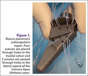
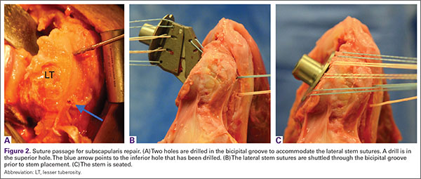
The 4 sutures passing through the medial calcar of the stem result in 8 suture limbs (limbs 1 through 8). Each limb is separately passed through the subscapularis tendon with a free needle, moving obliquely from inferior-medial to superior-lateral (Figure 3). Note: A variation is to pass 2 suture limbs at a time, but this technique has not been biomechanically investigated at the time of this writing.
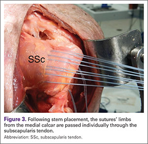
Prior to tying the sutures, it is helpful to place a stitch between the superolateral corner of the subscapularis and the anterior supraspinatus in order to facilitate reduction. The suture limbs are then tied with a specific sequence to create a suture-bridging construct with 2 additional medial mattress sutures as follows (Figures 4A, 4B):
1 to A
4 to C
5 to B
8 to D
2 to 3
6 to 7
In this technique, each suture limb is tied to a limb from another suture. When the last 2 pairs are tied (2 to 3 and 6 to 7), they are tensioned to remove any slack from the repair and equalize tension within all suture pairs. After the sutures are tied, the rotator interval may be closed with simple sutures if desired. The patient is immobilized in a sling for 4 to 6 weeks. Immediate passive forward flexion is allowed as well as external rotation to 30°. Strengthening is initiated at 8 weeks.
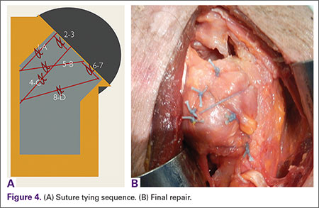
Discussion
The incidence of TSA has increased dramatically in the last decade and is projected to continue in the coming years.4 In the majority of cases, TSA leads to improvement in pain and function. However, failures continue to exist. In addition to glenoid loosening, prosthetic instability and rotator cuff insufficiency are the most common causes of failure.5 The latter 2 are intimately related since glenohumeral stability depends largely upon the rotator cuff. Therefore, optimization of outcome following TSA depends largely upon maintaining integrity of the rotator cuff. While the incidence of preoperative rotator cuff tears and fatty degeneration of the rotator are not modifiable, the management of the subscapularis is in the hands of the surgeon.
While subscapularis tenotomy has historically been used to access the glenohumeral joint during TSA, this approach is associated with an alarmingly high failure rate. Jackson and colleagues1 reported that 7 out of 15 (47%) of subscapularis tendons managed with tenotomy during TSA were completely torn on postoperative ultrasound. The patients with postoperative rupture had decreased internal rotation strength and DASH scores (4.6 intact vs. 25 ruptured; P = .04) compared to the patients with an intact tendon. Scalise and colleagues2 retrospectively compared a tenotomy approach to a LTO. They reported that 7 out of 15 subscapularis tenotomies were ruptured or attenuated postoperatively. By comparison, 18 out of 20 LTOs were healed. Regardless of approach, functional outcome was higher at 1 year postoperative when the subscapularis was intact.
The high failure rate with tendon-to-tendon healing following tenotomy has led to interest in a subscapularis peel to achieve tendon-to-bone healing or an LTO approach to achieve bone-to-bone healing. Lapner and colleagues3 compared a peel to an LTO in a randomized controlled trial of 87 patients. At 2 years postoperative, there was no difference in functional outcome between the 2 groups.
While both a peel and an LTO approach can be repaired with the technique described in this article, there are advantages to a peel approach. First, a peel approach may be considered more reproducible, particularly for surgeons who do a limited amount of shoulder arthroplasty. Whereas an LTO can vary in size, the subscapularis can nearly always be reproducibly peeled from the lesser tuberosity. Second, this technique uses a short stem, which relies upon proximal fixation. While this approach is bone-preserving, a large osteotomy has the potential to compromise fixation of the stem. Therefore, while one of us (PJD) uses a fleck LTO with a short stem, we advise a peel technique in most cases.
In summary, the subscapularis repair technique described here provides a reproducible and biomechanically sound approach to managing the subscapularis during TSA.
1. Jackson JD, Cil A, Smith J, Steinmann SP. Integrity and function of the subscapularis after total shoulder arthroplasty. J Shoulder Elbow Surg. 2010;19(7):1085-1090.
2. Scalise JJ, Ciccone J, Iannotti JP. Clinical, radiographic, and ultrasonographic comparison of subscapularis tenotomy and lesser tuberosity osteotomy for total shoulder arthroplasty. J Bone Joint Surg Am. 2010;92(7):1627-1634.
3. Lapner PL, Sabri E, Rakhra K, Bell K, Athwal GS. Comparison of lesser tuberosity osteotomy to subscapularis peel in shoulder arthroplasty: a randomized controlled trial. J Bone Joint Surg Am. 2012;94(24):2239-2246.
4. Kim SH, Wise BL, Zhang Y, Szabo RM. Increasing incidence of shoulder arthroplasty in the United States. J Bone Joint Surg Am. 2011;93(24):2249-2254.
5. Australian Orthopaedic Association National Joint Replacement Registry. Shoulder Arthroplasty 2015 Annual Report. https://aoanjrr.sahmri.com/documents/10180/217645/Shoulder%20Arthroplasty. Accessed April 7, 2016.
Subscapularis integrity following total shoulder arthroplasty (TSA) is important to maintaining glenohumeral joint stability and functional outcome. In recent years increased emphasis has been placed on the management of the subscapularis during TSA. Options for management of the subscapularis during TSA include tenotomy, release of the tendon from the bone (peel technique), or a lesser tuberosity osteotomy (LTO). Several studies have demonstrated that subscapularis integrity is often impaired with a traditional tenotomy approach.1,2 Based on these studies, a subscapularis peel or LTO approach have gained popularity.3 This technical article describes a subscapularis peel repair technique that is integrated into a press-fit anatomical short-stem during TSA.
Technique
The repair technique demonstrated in this article features the Univers Apex (Arthrex) humeral stem, but it can be adapted to other stems with features that allow for the incorporation of sutures.
A standard deltopectoral approach is used to gain access to the shoulder. The biceps tendon is released or tenotomized to gain access to the bicipital groove. The rotator interval is then opened beginning at the superior subscapularis by following the course of the anterior side of the proximal biceps and then directing the release toward the base of the coracoid in order to protect the supraspinatus tendon. Next, the subscapularis is sharply released from the lesser tuberosity. The tendon and capsule are released as a unit and a 3-sided release of the subscapularis is performed.
The humeral canal is opened with a reamer and broached to accommodate an appropriately sized press-fit component. A polyethylene glenoid component is placed and then attention is returned to the humerus.
Prior to placement of the humeral stem, 6 No. 2 or No. 5 FiberWire (Arthrex) sutures are pre-placed through suture holes in the stem (Figure 1). Four sutures are passed by hand through the medial calcar component and 2 sutures are placed through holes in the lateral portion of the stem. A 2.0-mm or 2.5-mm drill is used to create 2 holes in the bicipital groove: 1 at the superior aspect of the lesser tuberosity, and 1 at the inferior aspect of the lesser tuberosity (Figure 2A). Prior to impacting the stem, the 4 lateral suture limbs (limbs A through D) are shuttled through the holes in the bicipital groove (Figure 2B). Then the stem is impacted and secured, the final humeral head is placed, the joint is reduced, and the subscapularis is repaired (Figure 2C).
The 4 sutures passing through the medial calcar of the stem result in 8 suture limbs (limbs 1 through 8). Each limb is separately passed through the subscapularis tendon with a free needle, moving obliquely from inferior-medial to superior-lateral (Figure 3). Note: A variation is to pass 2 suture limbs at a time, but this technique has not been biomechanically investigated at the time of this writing.
Prior to tying the sutures, it is helpful to place a stitch between the superolateral corner of the subscapularis and the anterior supraspinatus in order to facilitate reduction. The suture limbs are then tied with a specific sequence to create a suture-bridging construct with 2 additional medial mattress sutures as follows (Figures 4A, 4B):
1 to A
4 to C
5 to B
8 to D
2 to 3
6 to 7
In this technique, each suture limb is tied to a limb from another suture. When the last 2 pairs are tied (2 to 3 and 6 to 7), they are tensioned to remove any slack from the repair and equalize tension within all suture pairs. After the sutures are tied, the rotator interval may be closed with simple sutures if desired. The patient is immobilized in a sling for 4 to 6 weeks. Immediate passive forward flexion is allowed as well as external rotation to 30°. Strengthening is initiated at 8 weeks.
Discussion
The incidence of TSA has increased dramatically in the last decade and is projected to continue in the coming years.4 In the majority of cases, TSA leads to improvement in pain and function. However, failures continue to exist. In addition to glenoid loosening, prosthetic instability and rotator cuff insufficiency are the most common causes of failure.5 The latter 2 are intimately related since glenohumeral stability depends largely upon the rotator cuff. Therefore, optimization of outcome following TSA depends largely upon maintaining integrity of the rotator cuff. While the incidence of preoperative rotator cuff tears and fatty degeneration of the rotator are not modifiable, the management of the subscapularis is in the hands of the surgeon.
While subscapularis tenotomy has historically been used to access the glenohumeral joint during TSA, this approach is associated with an alarmingly high failure rate. Jackson and colleagues1 reported that 7 out of 15 (47%) of subscapularis tendons managed with tenotomy during TSA were completely torn on postoperative ultrasound. The patients with postoperative rupture had decreased internal rotation strength and DASH scores (4.6 intact vs. 25 ruptured; P = .04) compared to the patients with an intact tendon. Scalise and colleagues2 retrospectively compared a tenotomy approach to a LTO. They reported that 7 out of 15 subscapularis tenotomies were ruptured or attenuated postoperatively. By comparison, 18 out of 20 LTOs were healed. Regardless of approach, functional outcome was higher at 1 year postoperative when the subscapularis was intact.
The high failure rate with tendon-to-tendon healing following tenotomy has led to interest in a subscapularis peel to achieve tendon-to-bone healing or an LTO approach to achieve bone-to-bone healing. Lapner and colleagues3 compared a peel to an LTO in a randomized controlled trial of 87 patients. At 2 years postoperative, there was no difference in functional outcome between the 2 groups.
While both a peel and an LTO approach can be repaired with the technique described in this article, there are advantages to a peel approach. First, a peel approach may be considered more reproducible, particularly for surgeons who do a limited amount of shoulder arthroplasty. Whereas an LTO can vary in size, the subscapularis can nearly always be reproducibly peeled from the lesser tuberosity. Second, this technique uses a short stem, which relies upon proximal fixation. While this approach is bone-preserving, a large osteotomy has the potential to compromise fixation of the stem. Therefore, while one of us (PJD) uses a fleck LTO with a short stem, we advise a peel technique in most cases.
In summary, the subscapularis repair technique described here provides a reproducible and biomechanically sound approach to managing the subscapularis during TSA.
1. Jackson JD, Cil A, Smith J, Steinmann SP. Integrity and function of the subscapularis after total shoulder arthroplasty. J Shoulder Elbow Surg. 2010;19(7):1085-1090.
2. Scalise JJ, Ciccone J, Iannotti JP. Clinical, radiographic, and ultrasonographic comparison of subscapularis tenotomy and lesser tuberosity osteotomy for total shoulder arthroplasty. J Bone Joint Surg Am. 2010;92(7):1627-1634.
3. Lapner PL, Sabri E, Rakhra K, Bell K, Athwal GS. Comparison of lesser tuberosity osteotomy to subscapularis peel in shoulder arthroplasty: a randomized controlled trial. J Bone Joint Surg Am. 2012;94(24):2239-2246.
4. Kim SH, Wise BL, Zhang Y, Szabo RM. Increasing incidence of shoulder arthroplasty in the United States. J Bone Joint Surg Am. 2011;93(24):2249-2254.
5. Australian Orthopaedic Association National Joint Replacement Registry. Shoulder Arthroplasty 2015 Annual Report. https://aoanjrr.sahmri.com/documents/10180/217645/Shoulder%20Arthroplasty. Accessed April 7, 2016.
Atopic dermatitis early in childhood tied to increased risk of autism, ADHD
Children who are diagnosed with atopic dermatitis before the age of 2 are more likely to be diagnosed with autism spectrum disorder or attention-deficit/hyperactivity disorder, according to Tzu-Chu Liao and associates.
Of the 387,262 children diagnosed with atopic dermatitis (AD) before the age of 2 included in the study, 0.5% were diagnosed with autism spectrum disorder (ASD), and 3.7% were diagnosed with attention-deficit/hyperactivity disorder (ADHD). In the control group, 0.4% were diagnosed with ASD, and 2.9% were diagnosed with ADHD. The hazard ratios for children exposed to atopic disorders before the age of 2 were 1.1 for ASD and 1.16 for ADHD.
Among children diagnosed early with AD, being male was the most significant risk factor for developing ASD (HR, 4.92) or ADHD (HR, 3.28). An urban/suburban residence was also a significant risk factor, as was persistent AD and emerging atopic respiratory disease in childhood.
“These findings suggest a possible etiologic communality between the diagnosis of allergic disorders along with comorbid ASD or ADHD. The atopic diathesis approach might influence the attention of child psychiatrists and pediatricians toward the diagnosis of ASD and ADHD. Further attention should be given to the management of allergic manifestations when treating symptoms of ASD and ADHD,” the investigators concluded.
Find the study in the Journal of Pediatrics (doi: 10.1016/j.jpeds.2015.12.063).
FROM THE JOURNAL OF PEDIATRICS
Proximal Periprosthetic Femur Fractures: Strategies for Internal Fixation
The rate of total hip arthroplasty (THA) is rising and demand is expected to increase by 174% to 572,000 by 2030.1 The rate of periprosthetic fracture around primary THA is frequently reported at around 1%,2-4 though a recent study of over 32,000 THAs quotes the 20-year probability of periprosthetic fracture at 3.5%.5 Revision THA is also increasing in frequency and associated rates of periprosthetic fracture range from 1.5% to 7.8% following revision THA,3,4,6 with the probability of fracture at 20 years of 11%.7 Projection models predict that the number of periprosthetic fractures will rise by 4.6% per decade over the next 30 years.8
Broadly, treatment options include open reduction internal fixation (ORIF), revision THA, and combined approaches. The Vancouver classification, based on fracture location, stem stability, and bone loss, is often used to guide fracture treatment, with stable implants treated with ORIF and unstable implants requiring revision arthroplasty.
Fixation strategies for treatment of periprosthetic fracture around a well-fixed arthroplasty stem have evolved over time, and there continue to be a variety of available internal fixation options with no clear consensus on the optimal strategy.9 Rates of reoperation following ORIF of periprosthetic femur fracture are reported from 13% to 23%,8,10-12 confirming that there remains room for improvement in management of these injuries.
Locking Plate Fixation
Early fixation strategies included allograft and cables alone as well as nonlocked plate and cerclage constructs. In response to the complication and reoperation rate for nonlocked plate constructs, reported at 33%,13 locking plates were introduced as a treatment option, allowing for both improved osseous vascularity and added screw options.14 When compared to the traditional nonlocked Ogden construct, locking plate constructs are more resistant to axial and torsional load.15 Clinically, the relative risk of nonunion after nonlocking plate fixation is reported at 11.9 times that of fixation with locking plate technology.16
Successful use of lateral locking plate fixation for treatment of this injury has been reported on in several clinical series.17-20 Froberg and colleagues12 evaluated 60 Vancouver B1 and C fractures treated by locking plate osteosynthesis and reported no nonunions, an improvement from previous constructs. However, 8 out of 60 patients with 2-year follow-up required reoperation—4 for infection, 3 for refracture, and 1 for stem loosening—making it clear that the locking plate alone was not a panacea.
With locking plate fixation a mainstay of modern treatment of periprosthetic femur fractures, many questions still remain.
Proximal Fixation
Even with the introduction of locked plates, treatment success after ORIF of Vancouver B1 fractures relies on adequate proximal fixation. Options for proximal fixation around the stem include cerclage wires or cables, unicortical locked screws, obliquely directed bicortical screws, and use of the locking attachment plate to insert bicortical locked screws. These strategies can be used in the presence of cemented or uncemented stems, with biomechanical evidence that screw fixation through the cement mantle does not cause failure.21
Several biomechanical studies address the stiffness and strength of varying proximal fixation strategies. While early fixation relied heavily on cables, the use of cables alone as proximal fixation has been linked to significantly higher rates of failure when compared to other constructs in a large clinical series.11 Multiple biomechanical studies have shown that newer methods of proximal fixation provide more rigid constructs.22,23
Unicortical locked screws appear to outperform cables biomechanically. The use of unicortical screws in lieu of or in addition to cables provides added resistance to lateral bending as well as torsion when compared to cables alone.24 A second group found that unicortical locked screws alone were superior to combined fixation with cerclage wires and unicortical locked screws.25
Added stability can be demonstrated by bicortical fixation strategies, which offer increased rigidity when compared to cables or unicortical screws.22 In vitro work has shown enhanced fixation stability with bicortical screw fixation using the locking attachment plate when compared to cerclage wires alone.23,26 Clinically, some authors have demonstrated success with the use of reversed distal femoral locking plates in order to enhance proximal locking options and allow for bicortical fixation around the stem.19 As noted above, the data favor the opinion that clinical failure rates with cerclage wires alone are high, and biomechanically, bicortical fixation around the femoral stem appears to be superior to unicortical locked screw fixation or cerclage wires. If rigid proximal fixation is desired, an effort should be made to obtain bicortical fixation around the femoral stem.
Allograft
Allograft strut, either alone or in addition to plate osteosynthesis, has long been used in treatment of periprosthetic fractures. Proponents of this technique cite improved biomechanical stability17 and allograft incorporation resulting in restoration of bone stock.
Early treatment of periprosthetic femur fractures consisted solely of allograft and cable fixation, but data on the technique is limited. A small series reported reasonable success, with only 2 out of 19 patients developing nonunion.27 More recently Haddad and colleagues28 reported malunions in 3 out of 19 patients treated with allograft and cables alone. Allograft alone has been largely abandoned in favor of plate fixation, and biomechanical evidence shows that plate and screw or cerclage constructs are more resistant to torsion and lateral bending than allograft with cables alone.29
However, the role of allograft in treatment of periprosthetic femur fractures is not clearly defined. Some authors advocate routinely supplementing plate fixation with allograft28,30 and others go as far as to suggest superior union rates of strut allograft augmented plate fixation when compared to plate fixation alone for periprosthetic fractures around a stable femoral stem.31 However, in that series, the failure rate of 5/11 patients treated with plate alone is higher than current series,12 and others have demonstrated good success without allograft, even with nonlocked plates.32
As recently as 2016, a lateral locking plate supplemented with allograft has been described as a successful technique, with no nonunions reported in a small series.30 However, without a comparison group, it is unclear what role the allograft plays in success in that construct.
Despite some proposed benefits, the additional soft tissue stripping required to place allograft has raised the question of delayed healing and increased infection rate as a result of this technique. A systematic review by Moore and colleagues33 looking at the use of allograft strut in Vancouver B1 fractures found increased time to union (4.4 vs 6.6 months) and deep infection rate (3.8% vs 8.3%) with the use of allograft strut, leading them to recommend cautious use of allograft when treating Vancouver B1 fractures.
With improved fixation strategies available, the role of allograft may be best reserved for patients with inadequate bone stock.
Dual Plate Fixation
Dual plate fixation has been proposed as one mechanism to increase construct strength. A periprosthetic fracture model has shown that, biomechanically, orthogonal plates have higher bending stiffness, torsional stiffness, cycles to failure, and load to failure when compared to a single lateral plate with use of a locking attachment plate proximally.34 Choi and colleagues35 compared lateral locking plates alone, lateral locking plates with allograft, and lateral locking plates with an orthogonal anterior plate and found the addition of an anterior plate resulted in the strongest construct.
Clinically, Müller and colleagues36 reported on a series of 10 patients treated with orthogonal (anterior and lateral) plating for periprosthetic femur fractures, including 3 nonunions. In their series, there was 1 plate failure and they conclude that dual plating is not associated with an increased risk of complications, and can also be used as a salvage procedure.
While the evidence for dual plating is limited, it may provide needed additional stability in certain cases without the added cost and exposure required for allograft.
Minimally Invasive Plate Osteosynthesis
Contrary to the extensive exposure required to place allograft, minimally invasive plate osteosynthesis (MIPO) of periprosthetic femur fractures is advocated by some authors.18,20 Ricci and colleagues18 reported no nonunions in 50 patients treated with indirect reduction techniques and laterally based plating alone without use of allograft. A combination of cables, locking, and nonlocking screws were used. Critical to their technique was preservation of the soft tissue envelope at the level of the fracture.
In further support of MIPO techniques, a systematic review of 1571 periprosthetic hip fractures reported significantly increased risk of nonunion with open approaches when compared to minimally invasive osteosynthesis,16 emphasizing the role of preservation of vascularity in treating these fractures.
Length of Fixation
For some time it was recommended that fixation of Vancouver B1 fractures end 2 cortical diameters below the level of the fracture.37,38 More recently there has been interest in the potential benefits of increased length of fixation.
A biomechanical study comparing long (20-hole) and short (12-hole) plates for periprosthetic fracture with regard to failure found no difference in failure rates between groups.39 While plate length did not appear to affect construct stiffness, the issue of subsequent fracture distal to the construct remains.
Moloney and colleagues40 proposed fixation of Vancouver B1 fractures using plates that span the length of the femur to the level of the femoral condyles to minimize peri-implant failures in osteoporotic patients. In 36 patients treated with standard-length plates, there were 2 fractures distal to the previous fixation compared to no subsequent fractures in 21 patients treated with spanning fixation.
Similarly, in Vancouver C fractures there is some evidence that fixation should span the femoral stem, regardless of available bone for fixation proximal to the fracture. Kubiak and colleagues41 found increasing load to failure and decreased cortical strain in a biomechanical model comparing plates that stop short of the femoral stem with those that span the stem.
Clinically, this concept is supported by Froberg and colleagues.12 In their series of 60 Vancouver B1 and C fractures treated with laterally based locked plating, 3 patients went on to refracture. All of these fractures occurred in patients with Vancouver C fractures treated with plates overlapping the preexisting stem by <50%. The fractures all occurred at the high stress area between the tip of the stem and the end of the plate.
Further support of extended plate length comes from Drew and colleagues,8 who demonstrated a significantly decreased risk of reoperation following ORIF of periprosthetic femur fracture when >75% of the length of the femur was spanned compared to <50%. Although in some settings short fixation may produce satisfactory results, consideration should be given to extending the length of fixation, especially in the osteoporotic population.
Interprosthetic Fractures
With a rising number of patients with ipsilateral hip and knee arthroplasty, the rate of interprosthetic fractures is rising. These fractures present additional challenges given preexisting implants above and below the level of the fracture. The use of a single precontoured laterally based locked plate has been reported with good union rates approaching 90%.42,43 In one series, all nonunions occurred in Vancouver B1 fractures,43 again bringing to light the challenging nature of the B1 fracture.
Nonunion
Success in treating periprosthetic femur fractures has improved with improved fixation methods and understanding of technique. However, current rates of nonunion are still reported up to 27% for B1 and C fractures.44
There is limited evidence on the treatment of periprosthetic femur fracture nonunion. However, treatment is difficult and complication rates are high. Crockarell and colleagues45 reported a 52% overall complication rate in their series of 23 periprosthetic femur fracture nonunions.
Nonunions of the femur near a prosthesis can be treated by revision of the fracture fixation using compression and grafting to achieve bone healing vs revision of the joint prosthesis to span the area of the nonunited bone. Case-by-case decision-making is based on the remaining bone stock and the type of revision prosthesis necessary to span the problem area. Given the challenges associated with their treatment, a focus on prevention of nonunion is of paramount importance.
Authors’ Preferred Treatment
Our treatment of periprosthetic femur fractures with a well-fixed hip arthroplasty stem adheres to the principles supported in the literature (Figures 1A-1D and Figures 2A, 2B).
- Soft tissue friendly dissection with limited exposure at the fracture site is preferred as the fracture allows, particularly in cases with comminution where a direct assessment of the reduction is not available.
- Plate fixation strategy is dictated by the characteristics of the fracture. Fracture patterns amenable to anatomic reduction receive interfragmentary compression and absolute stability constructs. Highly comminuted fractures receive relatively stable bridging constructs to encourage callous.
- Locking screws are used rarely in diaphyseal fracture patterns, and when employed, are applied to only one side of the fracture to limit “over stiffening” the construct.
- Liberal use of dual plating, both as a method of maintaining fracture reduction while a structural plate is applied and increasing construct rigidity.
- Proximal fixation relies heavily on bicortical screws placed through the holes of the lateral plate. Cerclage wires and unicortical screws are rarely used in our practice. In the case of larger stems, a bicortical 3.5-mm screw can be placed through a 4.5-mm plate using a reduction washer.
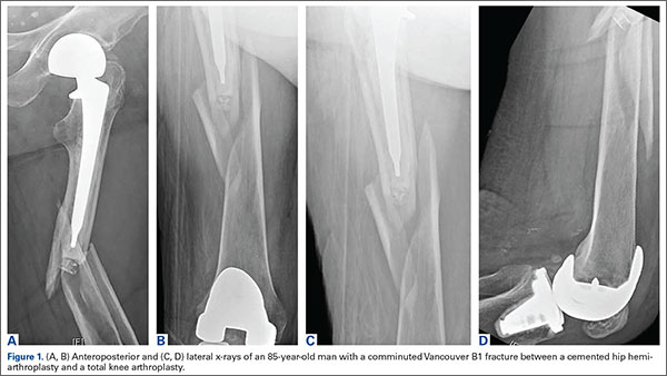
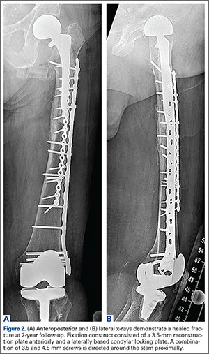
Summary
Techniques for treatment of periprosthetic femur fractures around a well-fixed hip arthroplasty stem are constantly evolving. Several principles have emerged to decrease rates of treatment failure and subsequent reoperation. While there are several methods to do so, it is critical to achieve stable proximal fixation. Long spanning fixation constructs are linked to lower failure and reoperation rates in both B1 and C type fractures. Additionally, the importance of soft tissue management and maintenance of local vascularity should not be underestimated.
1. Kurtz S, Ong K, Lau E, Mowat F, Halpern M. Projections of primary and revision hip and knee arthroplasty in the United States from 2005 to 2030. J Bone Joint Surg Am. 2007;89(4):780-785.
2. Lewallen DG, Berry DJ. Periprosthetic fracture of the femur after total hip arthroplasty: treatment and results to date. Instr Course Lect. 1998;47:243-249.
3. Kavanagh BF. Femoral fractures associated with total hip arthroplasty. Orthop Clin North Am. 1992;23(2):249-257.
4. Meek RM, Norwood T, Smith R, Brenkel IJ, Howie CR. The risk of peri-prosthetic fracture after primary and revision total hip and knee replacement. J Bone Joint Surg Br. 2011;93(1):96-101.
5. Abdel MP, Watts CD, Houdek MT, Lewallen DG, Berry DJ. Epidemiology of periprosthetic fracture of the femur in 32 644 primary total hip arthroplasties: a 40-year experience. Bone Joint J. 2016;98-B(4):461-467.
6. Berry DJ. Epidemiology: hip and knee. Orthop Clin North Am. 1999;30(2):183-190.
7. Abdel MP, Houdek MT, Watts CD, Lewallen DG, Berry DJ. Epidemiology of periprosthetic femoral fractures in 5417 revision total hip arthrolasties: a 40-year experience. Bone Joint J. 2016;98-B(4):468-474.
8. Drew JM, Griffin WL, Odum SM, Van Doren B, Weston BT, Stryker LS. Survivorship after periprosthetic femur fracture: factors affecting outcome. J Arthroplasty. 2015. [Epub ahead of print]
9. Dehghan N, McKee MD, Nauth A, Ristevski B, Schemitsch EH. Surgical fixation of Vancouver type B1 periprosthetic femur fractures: a systematic review. J Orthop Trauma. 2014;28(12):721-727.
10. Mukundan C, Rayan F, Kheir E, Macdonald D. Management of late periprosthetic femur fractures: a retrospective cohort of 72 patients. Int Orthop. 2010;34(4):485-489.
11. Lindahl H, Malchau H, Odén A, Garellick G. Risk factors for failure after treatment of a periprosthetic fracture of the femur. J Bone Joint Surg Br. 2006;88(1):26-30.
12. Froberg L, Troelsen A, Brix M. Periprosthetic Vancouver type B1 and C fractures treated by locking-plate osteosynthesis: fracture union and reoperations in 60 consecutive fractures. Acta Orthop. 2012;83(6):648-652.
13. Beals RK, Tower SS. Periprosthetic fractures of the femur. An analysis of 93 fractures. Clin Orthop Relat Res. 1996(327):238-246.
14. Perren SM. Evolution of the internal fixation of long bone fractures. The scientific basis of biological internal fixation: choosing a new balance between stability and biology. J Bone Joint Surg Br. 2002;84(8):1093-1110.
15. Fulkerson E, Koval K, Preston CF, Iesaka K, Kummer FJ, Egol KA. Fixation of periprosthetic femoral shaft fractures associated with cemented femoral stems: a biomechanical comparison of locked plating and conventional cable plates. J Orthop Trauma. 2006;20(2):89-93.
16. Stoffel K, Sommer C, Kalampoki V, Blumenthal A, Joeris A. The influence of the operation technique and implant used in the treatment of periprosthetic hip and interprosthetic femur fractures: a systematic literature review of 1571 cases. Arch Orthop Trauma Surg. 2016;136(4):553-561.
17. Fulkerson E, Tejwani N, Stuchin S, Egol K. Management of periprosthetic femur fractures with a first generation locking plate. Injury. 2007;38(8):965-972.
18. Ricci WM, Bolhofner BR, Loftus T, Cox C, Mitchell S, Borrelli J Jr. Indirect reduction and plate fixation, without grafting, for periprosthetic femoral shaft fractures about a stable intramedullary implant. Surgical technique. J Bone Joint Surg Am. 2006;88 Suppl 1 Pt 2:275-282.
19. Ebraheim NA, Gomez C, Ramineni SK, Liu J. Fixation of periprosthetic femoral shaft fractures adjacent to a well-fixed femoral stem with reversed distal femoral locking plate. J Trauma. 2009;66(4):1152-1157.
20. Bryant GK, Morshed S, Agel J, et al. Isolated locked compression plating for Vancouver Type B1 periprosthetic femoral fractures. Injury. 2009;40(11):1180-1186.
21. Giesinger K, Ebneter L, Day RE, Stoffel KK, Yates PJ, Kuster MS. Can plate osteosynthesis of periprosthethic femoral fractures cause cement mantle failure around a stable hip stem? A biomechanical analysis. J Arthroplasty. 2014;29(6):1308-1312.
22. Lewis GS, Caroom CT, Wee H, et al. Tangential bicortical locked fixation improves stability in vancouver B1 periprosthetic femur fractures: a biomechanical study. J Orthop Trauma. 2015;29(10):e364-e370.
23. Lenz M, Perren SM, Gueorguiev B, et al. A biomechanical study on proximal plate fixation techniques in periprosthetic femur fractures. Injury. 2014;45 Suppl 1:S71-S75.
24. Dennis MG, Simon JA, Kummer FJ, Koval KJ, DiCesare PE. Fixation of periprosthetic femoral shaft fractures occurring at the tip of the stem: a biomechanical study of 5 techniques. J Arthroplasty. 2000;15(4):523-528.
25. Graham SM, Mak JH, Moazen M, et al. Periprosthetic femoral fracture fixation: a biomechanical comparison between proximal locking screws and cables. J Orthop Sci. 2015;20(5):875-880.
26. Griffiths JT, Taheri A, Day RE, Yates PJ. Better axial stiffness of a bicortical screw construct compared to a cable construct for comminuted Vancouver B1 proximal femoral fractures. J Arthroplasty. 2015;30(12):2333-2337.
27. Chandler HP, King D, Limbird R, et al. The use of cortical allograft struts for fixation of fractures associated with well-fixed total joint prostheses. Semin Arthroplasty. 1993;4(2):99-107.
28. Haddad FS, Duncan CP, Berry DJ, Lewallen DG, Gross AE, Chandler HP. Periprosthetic femoral fractures around well-fixed implants: use of cortical onlay allografts with or without a plate. J Bone Joint Surg Am. 2002;84-A(6):945-950.
29. Dennis MG, Simon JA, Kummer FJ, Koval KJ, Di Cesare PE. Fixation of periprosthetic femoral shaft fractures: a biomechanical comparison of two techniques. J Orthop Trauma. 2001;15(3):177-180.
30. Yeo I, Rhyu KH, Kim SM, Park YS, Lim SJ. High union rates of locking compression plating with cortical strut allograft for type B1 periprosthetic femoral fractures. Int Orthop. 2016. [Epub ahead of print]
31. Khashan M, Amar E, Drexler M, Chechik Ok, Cohen Z, Steinberg EL. Superior outcome of strut allograft-augmented plate fixation for the treatment of periprosthetic fractures around a stable femoral stem. Injury. 2013;44(11):1556-1560.
32. Old AB, McGrory BJ, White RR, Babikian GM. Fixation of Vancouver B1 peri-prosthetic fractures by broad metal plates without the application of strut allografts. J Bone Joint Surg Br. 2006;88(11):1425-1429.
33. Moore RE, Baldwin K, Austin MS, Mehta S. A systematic review of open reduction and internal fixation of periprosthetic femur fractures with or without allograft strut, cerclage, and locked plates. J Arthroplasty. 2014;29(5):872-876.
34. Lenz M, Stoffel K, Gueorguiev B, Klos K, Kielstein H, Hofmann GO. Enhancing fixation strength in periprosthetic femur fractures by orthogonal plating-a biomechanical study. J Orthop Res. 2016;34(4):591-596.
35. Choi JK, Gardner TR, Yoon E, Morrison TA, Macaulay WB, Geller JA. The effect of fixation technique on the stiffness of comminuted Vancouver B1 periprosthetic femur fractures. J Arthroplasty. 2010;25(6 Suppl):124-128.
36. Müller FJ, Galler M Füchtmeier B. Clinical and radiological results of patients treated with orthogonal double plating for periprosthetic femoral fractures. Int Orthop. 2014;38(12):2469-2472.
37. Pike J, Davidson D, Garbuz D, Duncan CP, O’Brien PJ, Masri BA. Principles of treatment for periprosthetic femoral shaft fractures around well-fixed total hip arthroplasty. J Am Acad Orthop Surg. 2009;17(11):677-688.
38. Serocki JH, Chandler RW, Dorr LD. Treatment of fractures about hip prostheses with compression plating. J Arthroplasty. 1992;7(2):129-135.
39. Pletka JD, Marsland D, Belkoff SM, Mears SC, Kates SL. Biomechanical comparison of 2 different locking plate fixation methods in vancouver b1 periprosthetic femur fractures. Geriatr Orthop Surg Rehabil. 2011;2(2):51-55.
40. Moloney GB, Westrick ER, Siska PA, Tarkin IS. Treatment of periprosthetic femur fractures around a well-fixed hip arthroplasty implant: span the whole bone. Arch Orthop Trauma Surg. 2014;134(1):9-14.
41. Kubiak EN, Haller JM, Kemper DD, Presson AP, Higgins TF, Horowitz DS. Does the lateral plate need to overlap the stem to mitigate stress concentration when treating Vancouver C periprosthetic supracondylar femur fracture? J Arthroplasty. 2015;30(1):104-108.
42. Sah AP, Marshall A, Virkus WV, Estok DM 2nd, Della Valle CJ. Interprosthetic fractures of the femur: treatment with a single-locked plate. J Arthroplasty. 2010;25(2):280-286.
43. Hoffmann MF, Lotzien S, Schildhauer TA. Clinical outcome of interprosthetic femoral fractures treated with polyaxial locking plates. Injury. 2016. [Epub ahead of print]
44. Holder N, Papp S, Gofton W, Beaulé PE. Outcomes following surgical treatment of periprosthetic femur fractures: a single centre series. Can J Surg. 2014;57(3):209-213.
45. Crockarell JR Jr, Berry DJ, Lewallen DG. Nonunion after periprosthetic femoral fracture associated with total hip arthroplasty. J Bone Joint Surg Am. 1999;81(8):1073-1079.
The rate of total hip arthroplasty (THA) is rising and demand is expected to increase by 174% to 572,000 by 2030.1 The rate of periprosthetic fracture around primary THA is frequently reported at around 1%,2-4 though a recent study of over 32,000 THAs quotes the 20-year probability of periprosthetic fracture at 3.5%.5 Revision THA is also increasing in frequency and associated rates of periprosthetic fracture range from 1.5% to 7.8% following revision THA,3,4,6 with the probability of fracture at 20 years of 11%.7 Projection models predict that the number of periprosthetic fractures will rise by 4.6% per decade over the next 30 years.8
Broadly, treatment options include open reduction internal fixation (ORIF), revision THA, and combined approaches. The Vancouver classification, based on fracture location, stem stability, and bone loss, is often used to guide fracture treatment, with stable implants treated with ORIF and unstable implants requiring revision arthroplasty.
Fixation strategies for treatment of periprosthetic fracture around a well-fixed arthroplasty stem have evolved over time, and there continue to be a variety of available internal fixation options with no clear consensus on the optimal strategy.9 Rates of reoperation following ORIF of periprosthetic femur fracture are reported from 13% to 23%,8,10-12 confirming that there remains room for improvement in management of these injuries.
Locking Plate Fixation
Early fixation strategies included allograft and cables alone as well as nonlocked plate and cerclage constructs. In response to the complication and reoperation rate for nonlocked plate constructs, reported at 33%,13 locking plates were introduced as a treatment option, allowing for both improved osseous vascularity and added screw options.14 When compared to the traditional nonlocked Ogden construct, locking plate constructs are more resistant to axial and torsional load.15 Clinically, the relative risk of nonunion after nonlocking plate fixation is reported at 11.9 times that of fixation with locking plate technology.16
Successful use of lateral locking plate fixation for treatment of this injury has been reported on in several clinical series.17-20 Froberg and colleagues12 evaluated 60 Vancouver B1 and C fractures treated by locking plate osteosynthesis and reported no nonunions, an improvement from previous constructs. However, 8 out of 60 patients with 2-year follow-up required reoperation—4 for infection, 3 for refracture, and 1 for stem loosening—making it clear that the locking plate alone was not a panacea.
With locking plate fixation a mainstay of modern treatment of periprosthetic femur fractures, many questions still remain.
Proximal Fixation
Even with the introduction of locked plates, treatment success after ORIF of Vancouver B1 fractures relies on adequate proximal fixation. Options for proximal fixation around the stem include cerclage wires or cables, unicortical locked screws, obliquely directed bicortical screws, and use of the locking attachment plate to insert bicortical locked screws. These strategies can be used in the presence of cemented or uncemented stems, with biomechanical evidence that screw fixation through the cement mantle does not cause failure.21
Several biomechanical studies address the stiffness and strength of varying proximal fixation strategies. While early fixation relied heavily on cables, the use of cables alone as proximal fixation has been linked to significantly higher rates of failure when compared to other constructs in a large clinical series.11 Multiple biomechanical studies have shown that newer methods of proximal fixation provide more rigid constructs.22,23
Unicortical locked screws appear to outperform cables biomechanically. The use of unicortical screws in lieu of or in addition to cables provides added resistance to lateral bending as well as torsion when compared to cables alone.24 A second group found that unicortical locked screws alone were superior to combined fixation with cerclage wires and unicortical locked screws.25
Added stability can be demonstrated by bicortical fixation strategies, which offer increased rigidity when compared to cables or unicortical screws.22 In vitro work has shown enhanced fixation stability with bicortical screw fixation using the locking attachment plate when compared to cerclage wires alone.23,26 Clinically, some authors have demonstrated success with the use of reversed distal femoral locking plates in order to enhance proximal locking options and allow for bicortical fixation around the stem.19 As noted above, the data favor the opinion that clinical failure rates with cerclage wires alone are high, and biomechanically, bicortical fixation around the femoral stem appears to be superior to unicortical locked screw fixation or cerclage wires. If rigid proximal fixation is desired, an effort should be made to obtain bicortical fixation around the femoral stem.
Allograft
Allograft strut, either alone or in addition to plate osteosynthesis, has long been used in treatment of periprosthetic fractures. Proponents of this technique cite improved biomechanical stability17 and allograft incorporation resulting in restoration of bone stock.
Early treatment of periprosthetic femur fractures consisted solely of allograft and cable fixation, but data on the technique is limited. A small series reported reasonable success, with only 2 out of 19 patients developing nonunion.27 More recently Haddad and colleagues28 reported malunions in 3 out of 19 patients treated with allograft and cables alone. Allograft alone has been largely abandoned in favor of plate fixation, and biomechanical evidence shows that plate and screw or cerclage constructs are more resistant to torsion and lateral bending than allograft with cables alone.29
However, the role of allograft in treatment of periprosthetic femur fractures is not clearly defined. Some authors advocate routinely supplementing plate fixation with allograft28,30 and others go as far as to suggest superior union rates of strut allograft augmented plate fixation when compared to plate fixation alone for periprosthetic fractures around a stable femoral stem.31 However, in that series, the failure rate of 5/11 patients treated with plate alone is higher than current series,12 and others have demonstrated good success without allograft, even with nonlocked plates.32
As recently as 2016, a lateral locking plate supplemented with allograft has been described as a successful technique, with no nonunions reported in a small series.30 However, without a comparison group, it is unclear what role the allograft plays in success in that construct.
Despite some proposed benefits, the additional soft tissue stripping required to place allograft has raised the question of delayed healing and increased infection rate as a result of this technique. A systematic review by Moore and colleagues33 looking at the use of allograft strut in Vancouver B1 fractures found increased time to union (4.4 vs 6.6 months) and deep infection rate (3.8% vs 8.3%) with the use of allograft strut, leading them to recommend cautious use of allograft when treating Vancouver B1 fractures.
With improved fixation strategies available, the role of allograft may be best reserved for patients with inadequate bone stock.
Dual Plate Fixation
Dual plate fixation has been proposed as one mechanism to increase construct strength. A periprosthetic fracture model has shown that, biomechanically, orthogonal plates have higher bending stiffness, torsional stiffness, cycles to failure, and load to failure when compared to a single lateral plate with use of a locking attachment plate proximally.34 Choi and colleagues35 compared lateral locking plates alone, lateral locking plates with allograft, and lateral locking plates with an orthogonal anterior plate and found the addition of an anterior plate resulted in the strongest construct.
Clinically, Müller and colleagues36 reported on a series of 10 patients treated with orthogonal (anterior and lateral) plating for periprosthetic femur fractures, including 3 nonunions. In their series, there was 1 plate failure and they conclude that dual plating is not associated with an increased risk of complications, and can also be used as a salvage procedure.
While the evidence for dual plating is limited, it may provide needed additional stability in certain cases without the added cost and exposure required for allograft.
Minimally Invasive Plate Osteosynthesis
Contrary to the extensive exposure required to place allograft, minimally invasive plate osteosynthesis (MIPO) of periprosthetic femur fractures is advocated by some authors.18,20 Ricci and colleagues18 reported no nonunions in 50 patients treated with indirect reduction techniques and laterally based plating alone without use of allograft. A combination of cables, locking, and nonlocking screws were used. Critical to their technique was preservation of the soft tissue envelope at the level of the fracture.
In further support of MIPO techniques, a systematic review of 1571 periprosthetic hip fractures reported significantly increased risk of nonunion with open approaches when compared to minimally invasive osteosynthesis,16 emphasizing the role of preservation of vascularity in treating these fractures.
Length of Fixation
For some time it was recommended that fixation of Vancouver B1 fractures end 2 cortical diameters below the level of the fracture.37,38 More recently there has been interest in the potential benefits of increased length of fixation.
A biomechanical study comparing long (20-hole) and short (12-hole) plates for periprosthetic fracture with regard to failure found no difference in failure rates between groups.39 While plate length did not appear to affect construct stiffness, the issue of subsequent fracture distal to the construct remains.
Moloney and colleagues40 proposed fixation of Vancouver B1 fractures using plates that span the length of the femur to the level of the femoral condyles to minimize peri-implant failures in osteoporotic patients. In 36 patients treated with standard-length plates, there were 2 fractures distal to the previous fixation compared to no subsequent fractures in 21 patients treated with spanning fixation.
Similarly, in Vancouver C fractures there is some evidence that fixation should span the femoral stem, regardless of available bone for fixation proximal to the fracture. Kubiak and colleagues41 found increasing load to failure and decreased cortical strain in a biomechanical model comparing plates that stop short of the femoral stem with those that span the stem.
Clinically, this concept is supported by Froberg and colleagues.12 In their series of 60 Vancouver B1 and C fractures treated with laterally based locked plating, 3 patients went on to refracture. All of these fractures occurred in patients with Vancouver C fractures treated with plates overlapping the preexisting stem by <50%. The fractures all occurred at the high stress area between the tip of the stem and the end of the plate.
Further support of extended plate length comes from Drew and colleagues,8 who demonstrated a significantly decreased risk of reoperation following ORIF of periprosthetic femur fracture when >75% of the length of the femur was spanned compared to <50%. Although in some settings short fixation may produce satisfactory results, consideration should be given to extending the length of fixation, especially in the osteoporotic population.
Interprosthetic Fractures
With a rising number of patients with ipsilateral hip and knee arthroplasty, the rate of interprosthetic fractures is rising. These fractures present additional challenges given preexisting implants above and below the level of the fracture. The use of a single precontoured laterally based locked plate has been reported with good union rates approaching 90%.42,43 In one series, all nonunions occurred in Vancouver B1 fractures,43 again bringing to light the challenging nature of the B1 fracture.
Nonunion
Success in treating periprosthetic femur fractures has improved with improved fixation methods and understanding of technique. However, current rates of nonunion are still reported up to 27% for B1 and C fractures.44
There is limited evidence on the treatment of periprosthetic femur fracture nonunion. However, treatment is difficult and complication rates are high. Crockarell and colleagues45 reported a 52% overall complication rate in their series of 23 periprosthetic femur fracture nonunions.
Nonunions of the femur near a prosthesis can be treated by revision of the fracture fixation using compression and grafting to achieve bone healing vs revision of the joint prosthesis to span the area of the nonunited bone. Case-by-case decision-making is based on the remaining bone stock and the type of revision prosthesis necessary to span the problem area. Given the challenges associated with their treatment, a focus on prevention of nonunion is of paramount importance.
Authors’ Preferred Treatment
Our treatment of periprosthetic femur fractures with a well-fixed hip arthroplasty stem adheres to the principles supported in the literature (Figures 1A-1D and Figures 2A, 2B).
- Soft tissue friendly dissection with limited exposure at the fracture site is preferred as the fracture allows, particularly in cases with comminution where a direct assessment of the reduction is not available.
- Plate fixation strategy is dictated by the characteristics of the fracture. Fracture patterns amenable to anatomic reduction receive interfragmentary compression and absolute stability constructs. Highly comminuted fractures receive relatively stable bridging constructs to encourage callous.
- Locking screws are used rarely in diaphyseal fracture patterns, and when employed, are applied to only one side of the fracture to limit “over stiffening” the construct.
- Liberal use of dual plating, both as a method of maintaining fracture reduction while a structural plate is applied and increasing construct rigidity.
- Proximal fixation relies heavily on bicortical screws placed through the holes of the lateral plate. Cerclage wires and unicortical screws are rarely used in our practice. In the case of larger stems, a bicortical 3.5-mm screw can be placed through a 4.5-mm plate using a reduction washer.
Summary
Techniques for treatment of periprosthetic femur fractures around a well-fixed hip arthroplasty stem are constantly evolving. Several principles have emerged to decrease rates of treatment failure and subsequent reoperation. While there are several methods to do so, it is critical to achieve stable proximal fixation. Long spanning fixation constructs are linked to lower failure and reoperation rates in both B1 and C type fractures. Additionally, the importance of soft tissue management and maintenance of local vascularity should not be underestimated.
1. Kurtz S, Ong K, Lau E, Mowat F, Halpern M. Projections of primary and revision hip and knee arthroplasty in the United States from 2005 to 2030. J Bone Joint Surg Am. 2007;89(4):780-785.
2. Lewallen DG, Berry DJ. Periprosthetic fracture of the femur after total hip arthroplasty: treatment and results to date. Instr Course Lect. 1998;47:243-249.
3. Kavanagh BF. Femoral fractures associated with total hip arthroplasty. Orthop Clin North Am. 1992;23(2):249-257.
4. Meek RM, Norwood T, Smith R, Brenkel IJ, Howie CR. The risk of peri-prosthetic fracture after primary and revision total hip and knee replacement. J Bone Joint Surg Br. 2011;93(1):96-101.
5. Abdel MP, Watts CD, Houdek MT, Lewallen DG, Berry DJ. Epidemiology of periprosthetic fracture of the femur in 32 644 primary total hip arthroplasties: a 40-year experience. Bone Joint J. 2016;98-B(4):461-467.
6. Berry DJ. Epidemiology: hip and knee. Orthop Clin North Am. 1999;30(2):183-190.
7. Abdel MP, Houdek MT, Watts CD, Lewallen DG, Berry DJ. Epidemiology of periprosthetic femoral fractures in 5417 revision total hip arthrolasties: a 40-year experience. Bone Joint J. 2016;98-B(4):468-474.
8. Drew JM, Griffin WL, Odum SM, Van Doren B, Weston BT, Stryker LS. Survivorship after periprosthetic femur fracture: factors affecting outcome. J Arthroplasty. 2015. [Epub ahead of print]
9. Dehghan N, McKee MD, Nauth A, Ristevski B, Schemitsch EH. Surgical fixation of Vancouver type B1 periprosthetic femur fractures: a systematic review. J Orthop Trauma. 2014;28(12):721-727.
10. Mukundan C, Rayan F, Kheir E, Macdonald D. Management of late periprosthetic femur fractures: a retrospective cohort of 72 patients. Int Orthop. 2010;34(4):485-489.
11. Lindahl H, Malchau H, Odén A, Garellick G. Risk factors for failure after treatment of a periprosthetic fracture of the femur. J Bone Joint Surg Br. 2006;88(1):26-30.
12. Froberg L, Troelsen A, Brix M. Periprosthetic Vancouver type B1 and C fractures treated by locking-plate osteosynthesis: fracture union and reoperations in 60 consecutive fractures. Acta Orthop. 2012;83(6):648-652.
13. Beals RK, Tower SS. Periprosthetic fractures of the femur. An analysis of 93 fractures. Clin Orthop Relat Res. 1996(327):238-246.
14. Perren SM. Evolution of the internal fixation of long bone fractures. The scientific basis of biological internal fixation: choosing a new balance between stability and biology. J Bone Joint Surg Br. 2002;84(8):1093-1110.
15. Fulkerson E, Koval K, Preston CF, Iesaka K, Kummer FJ, Egol KA. Fixation of periprosthetic femoral shaft fractures associated with cemented femoral stems: a biomechanical comparison of locked plating and conventional cable plates. J Orthop Trauma. 2006;20(2):89-93.
16. Stoffel K, Sommer C, Kalampoki V, Blumenthal A, Joeris A. The influence of the operation technique and implant used in the treatment of periprosthetic hip and interprosthetic femur fractures: a systematic literature review of 1571 cases. Arch Orthop Trauma Surg. 2016;136(4):553-561.
17. Fulkerson E, Tejwani N, Stuchin S, Egol K. Management of periprosthetic femur fractures with a first generation locking plate. Injury. 2007;38(8):965-972.
18. Ricci WM, Bolhofner BR, Loftus T, Cox C, Mitchell S, Borrelli J Jr. Indirect reduction and plate fixation, without grafting, for periprosthetic femoral shaft fractures about a stable intramedullary implant. Surgical technique. J Bone Joint Surg Am. 2006;88 Suppl 1 Pt 2:275-282.
19. Ebraheim NA, Gomez C, Ramineni SK, Liu J. Fixation of periprosthetic femoral shaft fractures adjacent to a well-fixed femoral stem with reversed distal femoral locking plate. J Trauma. 2009;66(4):1152-1157.
20. Bryant GK, Morshed S, Agel J, et al. Isolated locked compression plating for Vancouver Type B1 periprosthetic femoral fractures. Injury. 2009;40(11):1180-1186.
21. Giesinger K, Ebneter L, Day RE, Stoffel KK, Yates PJ, Kuster MS. Can plate osteosynthesis of periprosthethic femoral fractures cause cement mantle failure around a stable hip stem? A biomechanical analysis. J Arthroplasty. 2014;29(6):1308-1312.
22. Lewis GS, Caroom CT, Wee H, et al. Tangential bicortical locked fixation improves stability in vancouver B1 periprosthetic femur fractures: a biomechanical study. J Orthop Trauma. 2015;29(10):e364-e370.
23. Lenz M, Perren SM, Gueorguiev B, et al. A biomechanical study on proximal plate fixation techniques in periprosthetic femur fractures. Injury. 2014;45 Suppl 1:S71-S75.
24. Dennis MG, Simon JA, Kummer FJ, Koval KJ, DiCesare PE. Fixation of periprosthetic femoral shaft fractures occurring at the tip of the stem: a biomechanical study of 5 techniques. J Arthroplasty. 2000;15(4):523-528.
25. Graham SM, Mak JH, Moazen M, et al. Periprosthetic femoral fracture fixation: a biomechanical comparison between proximal locking screws and cables. J Orthop Sci. 2015;20(5):875-880.
26. Griffiths JT, Taheri A, Day RE, Yates PJ. Better axial stiffness of a bicortical screw construct compared to a cable construct for comminuted Vancouver B1 proximal femoral fractures. J Arthroplasty. 2015;30(12):2333-2337.
27. Chandler HP, King D, Limbird R, et al. The use of cortical allograft struts for fixation of fractures associated with well-fixed total joint prostheses. Semin Arthroplasty. 1993;4(2):99-107.
28. Haddad FS, Duncan CP, Berry DJ, Lewallen DG, Gross AE, Chandler HP. Periprosthetic femoral fractures around well-fixed implants: use of cortical onlay allografts with or without a plate. J Bone Joint Surg Am. 2002;84-A(6):945-950.
29. Dennis MG, Simon JA, Kummer FJ, Koval KJ, Di Cesare PE. Fixation of periprosthetic femoral shaft fractures: a biomechanical comparison of two techniques. J Orthop Trauma. 2001;15(3):177-180.
30. Yeo I, Rhyu KH, Kim SM, Park YS, Lim SJ. High union rates of locking compression plating with cortical strut allograft for type B1 periprosthetic femoral fractures. Int Orthop. 2016. [Epub ahead of print]
31. Khashan M, Amar E, Drexler M, Chechik Ok, Cohen Z, Steinberg EL. Superior outcome of strut allograft-augmented plate fixation for the treatment of periprosthetic fractures around a stable femoral stem. Injury. 2013;44(11):1556-1560.
32. Old AB, McGrory BJ, White RR, Babikian GM. Fixation of Vancouver B1 peri-prosthetic fractures by broad metal plates without the application of strut allografts. J Bone Joint Surg Br. 2006;88(11):1425-1429.
33. Moore RE, Baldwin K, Austin MS, Mehta S. A systematic review of open reduction and internal fixation of periprosthetic femur fractures with or without allograft strut, cerclage, and locked plates. J Arthroplasty. 2014;29(5):872-876.
34. Lenz M, Stoffel K, Gueorguiev B, Klos K, Kielstein H, Hofmann GO. Enhancing fixation strength in periprosthetic femur fractures by orthogonal plating-a biomechanical study. J Orthop Res. 2016;34(4):591-596.
35. Choi JK, Gardner TR, Yoon E, Morrison TA, Macaulay WB, Geller JA. The effect of fixation technique on the stiffness of comminuted Vancouver B1 periprosthetic femur fractures. J Arthroplasty. 2010;25(6 Suppl):124-128.
36. Müller FJ, Galler M Füchtmeier B. Clinical and radiological results of patients treated with orthogonal double plating for periprosthetic femoral fractures. Int Orthop. 2014;38(12):2469-2472.
37. Pike J, Davidson D, Garbuz D, Duncan CP, O’Brien PJ, Masri BA. Principles of treatment for periprosthetic femoral shaft fractures around well-fixed total hip arthroplasty. J Am Acad Orthop Surg. 2009;17(11):677-688.
38. Serocki JH, Chandler RW, Dorr LD. Treatment of fractures about hip prostheses with compression plating. J Arthroplasty. 1992;7(2):129-135.
39. Pletka JD, Marsland D, Belkoff SM, Mears SC, Kates SL. Biomechanical comparison of 2 different locking plate fixation methods in vancouver b1 periprosthetic femur fractures. Geriatr Orthop Surg Rehabil. 2011;2(2):51-55.
40. Moloney GB, Westrick ER, Siska PA, Tarkin IS. Treatment of periprosthetic femur fractures around a well-fixed hip arthroplasty implant: span the whole bone. Arch Orthop Trauma Surg. 2014;134(1):9-14.
41. Kubiak EN, Haller JM, Kemper DD, Presson AP, Higgins TF, Horowitz DS. Does the lateral plate need to overlap the stem to mitigate stress concentration when treating Vancouver C periprosthetic supracondylar femur fracture? J Arthroplasty. 2015;30(1):104-108.
42. Sah AP, Marshall A, Virkus WV, Estok DM 2nd, Della Valle CJ. Interprosthetic fractures of the femur: treatment with a single-locked plate. J Arthroplasty. 2010;25(2):280-286.
43. Hoffmann MF, Lotzien S, Schildhauer TA. Clinical outcome of interprosthetic femoral fractures treated with polyaxial locking plates. Injury. 2016. [Epub ahead of print]
44. Holder N, Papp S, Gofton W, Beaulé PE. Outcomes following surgical treatment of periprosthetic femur fractures: a single centre series. Can J Surg. 2014;57(3):209-213.
45. Crockarell JR Jr, Berry DJ, Lewallen DG. Nonunion after periprosthetic femoral fracture associated with total hip arthroplasty. J Bone Joint Surg Am. 1999;81(8):1073-1079.

FDA evaluating the use of oral fluconazole in pregnancy
The Food and Drug Administration is reviewing the results of a Danish study that concludes there is a possible increased risk of miscarriage with the use of oral fluconazole (Diflucan) in pregnancy, according to a safety alert issued April 26.
The current drug label for oral fluconazole states that data from studies in women does not suggest an increased risk of problems during pregnancy or abnormalities in developing babies when women used a single 150-mg dose to treat vaginal yeast infections. However, reports of abnormalities at birth have resulted from high doses (400-800 mg/day) taken during pregnancy for much longer than a single dose. The Danish study had most pregnant women use one or two doses of 150 mg.
Oral fluconazole is used to treat yeast infections of the vaginal area, mouth, and esophagus. It can also be used to treat a fungal infection of the brain and spinal cord.
The FDA is also evaluating additional data and will make recommendations when the review is complete.
“Until FDA’s review is complete and more is understood about this study and other available data, FDA advises cautious prescribing of oral fluconazole in pregnancy,” the safety alert states.
The FDA also noted that the Centers for Disease Control and Prevention recommends using topical antifungal products only when treating pregnant women with vulvovaginal yeast infections.
Read more about the investigation on the FDA website.
Active Robotics for Total Hip Arthroplasty
Total hip arthroplasty (THA) is a successful surgery with positive clinical outcomes and over 95% survivorship at 10-year follow-up and 80% survivorship at 25-year follow-up.1,2 A hip replacement requires strong osteointegration3,4 to prevent femoral osteolysis, and correct implant alignment has been shown to correlate with prolonged implant survivorship and reduced dislocation.5,6 Robotics and computer-assisted navigation have been developed to increase the accuracy of implant placement and reduce outliers with the overall goal of improving long-term results. These technologies have shown significant improvements in implant positioning when compared to conventional techniques.7
The first active robotic system for use in orthopedic procedures, Robodoc (Think Surgical, Inc.), was based on a traditional computer-aided design/computer-aided manufacturing system. Currently, only 3 robotic systems for THA have clearance in the US: The Mako System (Stryker), Robodoc, and TSolution One (Think Surgical, Inc.). The TSolution One system is based on the legacy technology developed as Robodoc and currently provides assistance during preparation of the femoral canal as well as guidance and positioning assistance during acetabular cup reaming and implanting. The following is a summary of the author’s (DSD) preferred technique for robotic-assisted THA using TSolution One.
How It Works
The process begins with preoperative planning (Figure 1). A computed tomography (CT) scan is used to create a detailed 3-dimensional (3D) reconstruction of the patient’s pathologic hip anatomy. The CT scan images are uploaded to TPLAN, a preoperative planning station.
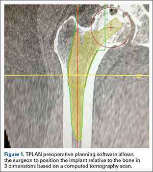
In TPLAN, the user creates a 3D template of the surgical plan for both the femoral and acetabular portions of the procedure. The system has an open platform, meaning that the user is not limited to a single implant design or manufacturer. The surgeon can control every aspect of implant positioning: rotation, anteversion, fit and fill on the femoral side and anteversion, inclination/lateral opening, and depth on the acetabular side. Additional features available to the surgeon include accurately defining bony deficits, identifying outlier implant sizes, and checking for excess native version. The system allows the surgeon to determine the native center of hip rotation, which can then be used during templating to give the patient a hip that feels natural because the native muscle tension is restored. Once the desired plan has been achieved, it is uploaded to the robot.The TCAT robot is an active system similar to those used in manufacturing assembly plants (eg, automobiles) in that it follows a predetermined path and can do so in an efficient manner. More specifically, once the user has defined the patient’s anatomy within its workspace, it will proceed with actively milling the femur as planned with sub-millimeter accuracy without the use of navigation. This is in contrast to a haptic system, where the user manually guides the robotic arm within a predefined boundary.
The acetabular portion of the procedure currently uses a standard reamer system and power tools, but the TCAT guides the surgeon to the planned cup orientation, which is maintained during reaming and impaction.
In the Operating Suite
Once in the operating suite, the plan is uploaded into TCAT. Confirmation of the plan and the patient are incorporated into the surgical “time out.” Currently, the system supports patient positioning in standard lateral decubitus using a posterior approach with a standard operating room table. A posterior approach is undertaken to expose and dislocate the hip, with retractors placed to protect the soft tissues and allow the robot its working space.
One procedural difference from the standard THA technique is that the femoral head is initially retained to fixate the femur relative to the robot. A 5-mm Schanz pin is placed in the femoral head and then rigidly attached to the base of the robot. During a process called registration, a series of points on the surface of the exposed bone are collected by the surgeon via a digitizer probe attached to the robot. The TCAT monitor will guide the surgeon through point collection using a map showing the patient’s 3D bone model generated from the CT scan. The software then “finds” the patient’s femur in space and matches it to the 3D CT plan. Milling begins with a burr spinning at 80,000 rpm and saline to irrigate and remove bone debris (Figure 2). The actual milling process takes 5 to 15 minutes, depending on the choice and size of the implant.
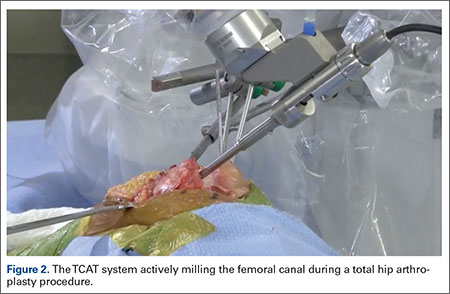
A bone motion monitor (BMM) is also attached to the femur, along with recovery markers (RM). The BMM immediately pauses the robot during any active bone milling if it senses femoral motion from the original position. The surgeon then touches the RM with the digitizer to re-register the bone’s position and resume the milling process.
Attention is then turned to the acetabular portion of the procedure. Again, the robot must be rigidly fixed to the patient’s pelvis, along with the RM. Once the surgeon has registered the acetabular position using the digitizer, the robotic arm moves into the preoperatively planned orientation. A universal quick-release allows the surgeon to attach a standard reamer to the robot arm and ream while the robot holds the reamer in place. Once the acetabular preparation is complete, the cup impactor is placed onto the robotic arm and the implant is impacted into the patient. Thereafter, the digitizer can be used to collect points on the surface of the cup and confirm the exact cup placement (Figure 3).
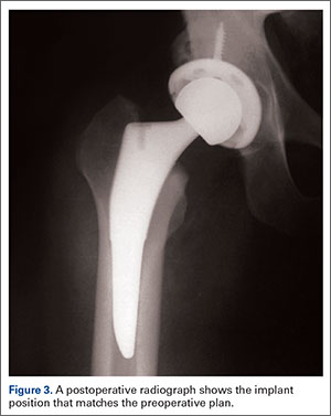
Outcomes
The legacy system, Robodoc, has been used in thousands of clinical cases for both THA and total knee arthroplasty. The Table represents a summary of the THA clinical studies during a time frame in which only the femoral portion of the procedure was available to surgeons.
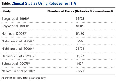
Bargar and colleagues8 describe the first Robodoc clinical trial in the US, along with the first 900 THA procedures performed in Germany. In the US, researchers conducted a prospective, randomized control study with 65 robotic cases and 62 conventional control cases. In terms of functional outcomes, there were no differences between the 2 groups. The robot group had improved radiographic fit and component positioning but significantly increased surgical time and blood loss. There were no femoral fractures in the robot group but 3 cases in the control group. In Germany, they reported on 870 primary THAs and 30 revision THA cases. For the primary cases, Harris hip scores rose from 43.7 preoperatively to 91.5 postoperatively. Complication rates were similar to conventional techniques, except the robot cases had no intraoperative femoral fractures.
Several prospective randomized clinical studies compared use of the Robodoc system with a conventional technique. The group studied by Honl and colleagues9 included 61 robotic cases and 80 conventional cases. The robot group had significant improvements in limb-length equality and varus-valgus orientation of the stem. When the revision cases were excluded, the authors found the Harris hip scores, prosthetic alignment, and limb length differentials were better for the robotic group at both 6 and 12 months.
Nakamura and colleagues10 looked at 75 robotic cases and 71 conventional cases. The results showed that at 2 and 3 years postoperatively, the robotic group had better Japanese Orthopaedic Association (JOA) scores, but by 5 years postoperatively, the differences were no longer significant. The robotic group had a smaller range for leg length inequality (0-12 mm) compared to the conventional group (0-29 mm). The results also showed that at both 2 and 5 years postoperatively, there was more significant stress shielding of the proximal femur, suggesting greater bone loss in the conventional group.
Nishihara and colleagues11 had 78 subjects in each of the robotic and conventional groups and found significantly better Merle d’Aubigné hip scores at 2 years postoperatively in the robotic group. The conventional group suffered 5 intraoperative fractures compared with none in the robotic group, along with greater estimated blood loss, an increased use of undersized stems, higher-than-expected vertical seating, and unexpected femoral anteversion. The robotic cases did, however, take 19 minutes longer than the conventional cases.
Hananouchi and colleagues12 looked at periprosthetic bone remodeling in 31 robotic hips and 27 conventional hips to determine whether load was effectively transferred from implant to bone after using the Robodoc system to prepare the femoral canal. Using dual energy X-ray absorptiometry (DEXA) to measure bone density, they found significantly less bone loss in the proximal periprosthetic areas in the robotic group compared to the conventional group; however, there were no differences in the Merle d’Aubigné hip scores.
Lim and colleagues13 looked specifically at alignment accuracy and clinical outcomes specifically for short femoral stem implants. In a group of 24 robotic cases and 25 conventional cases, they found significantly improved stem alignment and leg length inequality and no differences in Harris Hip score, Western Ontario and McMaster Universities Osteoarthritis Index (WOMAC) score, or complications at 24 months.
In 2004, Nishihara and colleagues14 evaluated the accuracy of femoral canal preparation using postoperative CT images for 75 cases of THA performed with the original pin-based version of Robodoc. The results showed that the differences between the preoperative plan and the postoperative CT were <5% in terms of canal fill, <1 mm in gap, and <1° in mediolateral and anteroposterior alignment with no reported fractures or complications. They concluded that the Robodoc system resulted in a high degree of accuracy.
Schulz and colleagues15 reported on 97 of 143 consecutive cases performed from 1997 to 2002. Technical complications were described in 9 cases. Five of the reported complications included the BMM pausing cutting as designed for patient safety, which led to re-registration, and slightly prolonged surgery. The remaining 4 complications included 2 femoral shaft fissures requiring wire cerclage, 1 case of damage to the acetabular rim from the milling device, and 1 defect of the greater trochanter that was milled. In terms of clinical results, they found that the complications, functional outcomes, and radiographic outcomes were comparable to conventional techniques. The rate of femoral shaft fissures, which had been zero in all other studies with Robodoc, was comparable to conventional technique.
Conclusion
The most significant change in hip arthroplasty until now has been the transition from a cemented technique to a press-fit or ingrowth prosthesis.16 The first robotic surgery was performed in the US in 1992 using the legacy system upon which the current TSolution One was based. Since then, the use of surgical robots has seen a 30% increase annually over the last decade in a variety of surgical fields.17 In orthopedics, specifically THA, the results have shown that robotics clearly offers benefits in terms of accuracy, precision, and reproducibility. These benefits will likely translate into improved long-term outcomes and increased survivorship in future studies.
1. Kurtz S, Ong K, Lau E, Mowat F, Halpern M. Projections of primary and revision hip and knee arthroplasty in the United States from 2005 to 2030. J Bone Joint Surg Am. 2007;89(4):780-785.
2. National Joint Registry. National Joint Registry for England and Wales. 7th annual report. Available at: http://www.njrcentre.org.uk/njrcentre/portals/0/njr%207th%20annual%20report%202010.pdf. Accessed April 12, 2016.
3. Paul HA, Bargar WL, Mittlestadt B, et al. Development of a surgical robot for cementless total hip arthroplasty. Clin Orthop Relat Res. 1992;285:57-66.
4. Bobyn JD, Engh CA. Human histology of bone-porous metal implant interface. Orthopedics. 1984;7(9):1410.
5. Barrack RL. Dislocation after total hip arthroplasty: Implant design and orientation. J Am Acad Orthop Surg. 2003;11(2):89-99.
6. Miki H, Sugano N, Yonenobu K, Tsuda K, Hattori M, Suzuki N. Detecting cause of dislocation after total hip arthroplasty by patient-specific four-dimensional motion analysis. Clin Biomech. 2013;28(2):182-186.
7. Sugano N. Computer-assisted orthopaedic surgery and robotic surgery in total hip arthroplasty. Clin Orthop Surg. 2013;5(1):1-9.
8. Bargar WL, Bauer A, Börner M. Primary and revision total hip replacement using the Robodoc system. Clin Orthop Rel Res. 1998;354:82-91.
9. Honl M, Dierk O, Gauck C, et al. Comparison of robotic-assisted and manual implantation of primary total hip replacement: a prospective study. J Bone Joint Surg Am. 2003;85-A(8):1470-1478.
10. Nakamura N, Sugano N, Nishii T, Kakimoto A, Miki H. A comparison between robotic-assisted and manual implantation of cementless total hip arthroplasty. Clin Orthop Relat Res. 2010;468(4):1072-1081.
11. Nishihara S, Sugano N, Nishii T, Miki H, Nakamura N, Yoshikawa H. Comparison between hand rasping and robotic milling for stem implantation in cementless total hip arthroplasty. J Arthroplasty. 2006;21(7):957-966.
12. Hananouchi T, Sugano N, Nishii T, et al. Effect of robotic milling on periprosthetic bone remodeling. J Orthop Res. 2007;25(8):1062-1069.
13. Lim SJ, Ko KR, Park CW, Moon YW, Park YS. Robot-assisted primary cementless total hip arthroplasty with a short femoral stem: a prospective randomized short-term outcome study. Comput Aided Surg. 2015;20(1):41-46.
14. Nishihara S, Sugano N, Nishii T, et al. Clinical accuracy evaluation of femoral canal preparation using the ROBODOC system. J Orthop Sci. 2004;9(5):452-461.
15. Schulz AP, Seide K, Queitsch C, et al. Results of total hip replacement using the Robodoc surgical assistant system: clinical outcome and evaluation of complications for 97 procedures. Int J Med Robot. 2007;3(4):301-306.
16. Wyatt M, Hooper G, Framptom C, Rothwell A. Survival outcomes of cemented compared to uncemented stems in primary total hip replacement. World J Orthop. 2014;5(5):591-596.
17. Howard B. Is robotic surgery right for you? AARP The Magazine. December 2013/January 2014. Available at: http://www.aarp.org/health/conditions-treatments/info-12-2013/robotic-surgery-risks-benefits.html. Accessed April 12, 2016.
Total hip arthroplasty (THA) is a successful surgery with positive clinical outcomes and over 95% survivorship at 10-year follow-up and 80% survivorship at 25-year follow-up.1,2 A hip replacement requires strong osteointegration3,4 to prevent femoral osteolysis, and correct implant alignment has been shown to correlate with prolonged implant survivorship and reduced dislocation.5,6 Robotics and computer-assisted navigation have been developed to increase the accuracy of implant placement and reduce outliers with the overall goal of improving long-term results. These technologies have shown significant improvements in implant positioning when compared to conventional techniques.7
The first active robotic system for use in orthopedic procedures, Robodoc (Think Surgical, Inc.), was based on a traditional computer-aided design/computer-aided manufacturing system. Currently, only 3 robotic systems for THA have clearance in the US: The Mako System (Stryker), Robodoc, and TSolution One (Think Surgical, Inc.). The TSolution One system is based on the legacy technology developed as Robodoc and currently provides assistance during preparation of the femoral canal as well as guidance and positioning assistance during acetabular cup reaming and implanting. The following is a summary of the author’s (DSD) preferred technique for robotic-assisted THA using TSolution One.
How It Works
The process begins with preoperative planning (Figure 1). A computed tomography (CT) scan is used to create a detailed 3-dimensional (3D) reconstruction of the patient’s pathologic hip anatomy. The CT scan images are uploaded to TPLAN, a preoperative planning station.
In TPLAN, the user creates a 3D template of the surgical plan for both the femoral and acetabular portions of the procedure. The system has an open platform, meaning that the user is not limited to a single implant design or manufacturer. The surgeon can control every aspect of implant positioning: rotation, anteversion, fit and fill on the femoral side and anteversion, inclination/lateral opening, and depth on the acetabular side. Additional features available to the surgeon include accurately defining bony deficits, identifying outlier implant sizes, and checking for excess native version. The system allows the surgeon to determine the native center of hip rotation, which can then be used during templating to give the patient a hip that feels natural because the native muscle tension is restored. Once the desired plan has been achieved, it is uploaded to the robot.The TCAT robot is an active system similar to those used in manufacturing assembly plants (eg, automobiles) in that it follows a predetermined path and can do so in an efficient manner. More specifically, once the user has defined the patient’s anatomy within its workspace, it will proceed with actively milling the femur as planned with sub-millimeter accuracy without the use of navigation. This is in contrast to a haptic system, where the user manually guides the robotic arm within a predefined boundary.
The acetabular portion of the procedure currently uses a standard reamer system and power tools, but the TCAT guides the surgeon to the planned cup orientation, which is maintained during reaming and impaction.
In the Operating Suite
Once in the operating suite, the plan is uploaded into TCAT. Confirmation of the plan and the patient are incorporated into the surgical “time out.” Currently, the system supports patient positioning in standard lateral decubitus using a posterior approach with a standard operating room table. A posterior approach is undertaken to expose and dislocate the hip, with retractors placed to protect the soft tissues and allow the robot its working space.
One procedural difference from the standard THA technique is that the femoral head is initially retained to fixate the femur relative to the robot. A 5-mm Schanz pin is placed in the femoral head and then rigidly attached to the base of the robot. During a process called registration, a series of points on the surface of the exposed bone are collected by the surgeon via a digitizer probe attached to the robot. The TCAT monitor will guide the surgeon through point collection using a map showing the patient’s 3D bone model generated from the CT scan. The software then “finds” the patient’s femur in space and matches it to the 3D CT plan. Milling begins with a burr spinning at 80,000 rpm and saline to irrigate and remove bone debris (Figure 2). The actual milling process takes 5 to 15 minutes, depending on the choice and size of the implant.
A bone motion monitor (BMM) is also attached to the femur, along with recovery markers (RM). The BMM immediately pauses the robot during any active bone milling if it senses femoral motion from the original position. The surgeon then touches the RM with the digitizer to re-register the bone’s position and resume the milling process.
Attention is then turned to the acetabular portion of the procedure. Again, the robot must be rigidly fixed to the patient’s pelvis, along with the RM. Once the surgeon has registered the acetabular position using the digitizer, the robotic arm moves into the preoperatively planned orientation. A universal quick-release allows the surgeon to attach a standard reamer to the robot arm and ream while the robot holds the reamer in place. Once the acetabular preparation is complete, the cup impactor is placed onto the robotic arm and the implant is impacted into the patient. Thereafter, the digitizer can be used to collect points on the surface of the cup and confirm the exact cup placement (Figure 3).
Outcomes
The legacy system, Robodoc, has been used in thousands of clinical cases for both THA and total knee arthroplasty. The Table represents a summary of the THA clinical studies during a time frame in which only the femoral portion of the procedure was available to surgeons.
Bargar and colleagues8 describe the first Robodoc clinical trial in the US, along with the first 900 THA procedures performed in Germany. In the US, researchers conducted a prospective, randomized control study with 65 robotic cases and 62 conventional control cases. In terms of functional outcomes, there were no differences between the 2 groups. The robot group had improved radiographic fit and component positioning but significantly increased surgical time and blood loss. There were no femoral fractures in the robot group but 3 cases in the control group. In Germany, they reported on 870 primary THAs and 30 revision THA cases. For the primary cases, Harris hip scores rose from 43.7 preoperatively to 91.5 postoperatively. Complication rates were similar to conventional techniques, except the robot cases had no intraoperative femoral fractures.
Several prospective randomized clinical studies compared use of the Robodoc system with a conventional technique. The group studied by Honl and colleagues9 included 61 robotic cases and 80 conventional cases. The robot group had significant improvements in limb-length equality and varus-valgus orientation of the stem. When the revision cases were excluded, the authors found the Harris hip scores, prosthetic alignment, and limb length differentials were better for the robotic group at both 6 and 12 months.
Nakamura and colleagues10 looked at 75 robotic cases and 71 conventional cases. The results showed that at 2 and 3 years postoperatively, the robotic group had better Japanese Orthopaedic Association (JOA) scores, but by 5 years postoperatively, the differences were no longer significant. The robotic group had a smaller range for leg length inequality (0-12 mm) compared to the conventional group (0-29 mm). The results also showed that at both 2 and 5 years postoperatively, there was more significant stress shielding of the proximal femur, suggesting greater bone loss in the conventional group.
Nishihara and colleagues11 had 78 subjects in each of the robotic and conventional groups and found significantly better Merle d’Aubigné hip scores at 2 years postoperatively in the robotic group. The conventional group suffered 5 intraoperative fractures compared with none in the robotic group, along with greater estimated blood loss, an increased use of undersized stems, higher-than-expected vertical seating, and unexpected femoral anteversion. The robotic cases did, however, take 19 minutes longer than the conventional cases.
Hananouchi and colleagues12 looked at periprosthetic bone remodeling in 31 robotic hips and 27 conventional hips to determine whether load was effectively transferred from implant to bone after using the Robodoc system to prepare the femoral canal. Using dual energy X-ray absorptiometry (DEXA) to measure bone density, they found significantly less bone loss in the proximal periprosthetic areas in the robotic group compared to the conventional group; however, there were no differences in the Merle d’Aubigné hip scores.
Lim and colleagues13 looked specifically at alignment accuracy and clinical outcomes specifically for short femoral stem implants. In a group of 24 robotic cases and 25 conventional cases, they found significantly improved stem alignment and leg length inequality and no differences in Harris Hip score, Western Ontario and McMaster Universities Osteoarthritis Index (WOMAC) score, or complications at 24 months.
In 2004, Nishihara and colleagues14 evaluated the accuracy of femoral canal preparation using postoperative CT images for 75 cases of THA performed with the original pin-based version of Robodoc. The results showed that the differences between the preoperative plan and the postoperative CT were <5% in terms of canal fill, <1 mm in gap, and <1° in mediolateral and anteroposterior alignment with no reported fractures or complications. They concluded that the Robodoc system resulted in a high degree of accuracy.
Schulz and colleagues15 reported on 97 of 143 consecutive cases performed from 1997 to 2002. Technical complications were described in 9 cases. Five of the reported complications included the BMM pausing cutting as designed for patient safety, which led to re-registration, and slightly prolonged surgery. The remaining 4 complications included 2 femoral shaft fissures requiring wire cerclage, 1 case of damage to the acetabular rim from the milling device, and 1 defect of the greater trochanter that was milled. In terms of clinical results, they found that the complications, functional outcomes, and radiographic outcomes were comparable to conventional techniques. The rate of femoral shaft fissures, which had been zero in all other studies with Robodoc, was comparable to conventional technique.
Conclusion
The most significant change in hip arthroplasty until now has been the transition from a cemented technique to a press-fit or ingrowth prosthesis.16 The first robotic surgery was performed in the US in 1992 using the legacy system upon which the current TSolution One was based. Since then, the use of surgical robots has seen a 30% increase annually over the last decade in a variety of surgical fields.17 In orthopedics, specifically THA, the results have shown that robotics clearly offers benefits in terms of accuracy, precision, and reproducibility. These benefits will likely translate into improved long-term outcomes and increased survivorship in future studies.
1. Kurtz S, Ong K, Lau E, Mowat F, Halpern M. Projections of primary and revision hip and knee arthroplasty in the United States from 2005 to 2030. J Bone Joint Surg Am. 2007;89(4):780-785.
2. National Joint Registry. National Joint Registry for England and Wales. 7th annual report. Available at: http://www.njrcentre.org.uk/njrcentre/portals/0/njr%207th%20annual%20report%202010.pdf. Accessed April 12, 2016.
3. Paul HA, Bargar WL, Mittlestadt B, et al. Development of a surgical robot for cementless total hip arthroplasty. Clin Orthop Relat Res. 1992;285:57-66.
4. Bobyn JD, Engh CA. Human histology of bone-porous metal implant interface. Orthopedics. 1984;7(9):1410.
5. Barrack RL. Dislocation after total hip arthroplasty: Implant design and orientation. J Am Acad Orthop Surg. 2003;11(2):89-99.
6. Miki H, Sugano N, Yonenobu K, Tsuda K, Hattori M, Suzuki N. Detecting cause of dislocation after total hip arthroplasty by patient-specific four-dimensional motion analysis. Clin Biomech. 2013;28(2):182-186.
7. Sugano N. Computer-assisted orthopaedic surgery and robotic surgery in total hip arthroplasty. Clin Orthop Surg. 2013;5(1):1-9.
8. Bargar WL, Bauer A, Börner M. Primary and revision total hip replacement using the Robodoc system. Clin Orthop Rel Res. 1998;354:82-91.
9. Honl M, Dierk O, Gauck C, et al. Comparison of robotic-assisted and manual implantation of primary total hip replacement: a prospective study. J Bone Joint Surg Am. 2003;85-A(8):1470-1478.
10. Nakamura N, Sugano N, Nishii T, Kakimoto A, Miki H. A comparison between robotic-assisted and manual implantation of cementless total hip arthroplasty. Clin Orthop Relat Res. 2010;468(4):1072-1081.
11. Nishihara S, Sugano N, Nishii T, Miki H, Nakamura N, Yoshikawa H. Comparison between hand rasping and robotic milling for stem implantation in cementless total hip arthroplasty. J Arthroplasty. 2006;21(7):957-966.
12. Hananouchi T, Sugano N, Nishii T, et al. Effect of robotic milling on periprosthetic bone remodeling. J Orthop Res. 2007;25(8):1062-1069.
13. Lim SJ, Ko KR, Park CW, Moon YW, Park YS. Robot-assisted primary cementless total hip arthroplasty with a short femoral stem: a prospective randomized short-term outcome study. Comput Aided Surg. 2015;20(1):41-46.
14. Nishihara S, Sugano N, Nishii T, et al. Clinical accuracy evaluation of femoral canal preparation using the ROBODOC system. J Orthop Sci. 2004;9(5):452-461.
15. Schulz AP, Seide K, Queitsch C, et al. Results of total hip replacement using the Robodoc surgical assistant system: clinical outcome and evaluation of complications for 97 procedures. Int J Med Robot. 2007;3(4):301-306.
16. Wyatt M, Hooper G, Framptom C, Rothwell A. Survival outcomes of cemented compared to uncemented stems in primary total hip replacement. World J Orthop. 2014;5(5):591-596.
17. Howard B. Is robotic surgery right for you? AARP The Magazine. December 2013/January 2014. Available at: http://www.aarp.org/health/conditions-treatments/info-12-2013/robotic-surgery-risks-benefits.html. Accessed April 12, 2016.
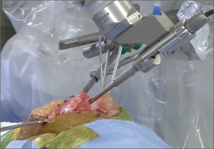
The Evolution of Image-Free Robotic Assistance in Unicompartmental Knee Arthroplasty
The concept of robotics is relatively new in medical practice. The term “robot” itself is less than 100 years old, having been first introduced to popular culture in 1917 by Joseph Capek in the science fiction story Opilec.1,2 Robots eventually transitioned from this initial fictional literary setting to reality in 1958, when General Motors began adding automated machines to its assembly lines.1 However, it was not until the 1980s that robotics and their exacting efficiencies would be introduced in the medical field, and it would take another decade before they would enter the specialty of orthopedics.1-4
The first robotic-assisted orthopedic surgery was reportedly performed in 1992, when the Robodoc autonomous system was utilized for total hip arthroplasty.2-4 A robotic system for total knee arthroplasty (TKA) was first described in 1993, but it would take several more years until a system for unicompartmental knee arthroplasty (UKA) would be commercialized and used clinically.5,6 The rationale for advancement of robotic technology for isolated medial or lateral knee arthritis stems from the recognition that while UKA is effective and durable when components and limb are well aligned and soft tissues appropriately balanced, they are less forgiving of even slight component malalignment of as little as 2° to 3° and prone to premature loosening or wear in those circumstances.7-13,14 In the mid 2000s, Cobb and colleagues6 reported using a semiautonomous robot for UKA. Since then, emergence of other semiautonomous robotic systems has led to greater market penetration and technology utilization.15
Currently, an estimated 15% to 20% of UKA surgeries are being performed with robotic assistance.16 Further, patent activity and peer-reviewed publications related to robotic technology in UKA (which can be considered surrogate measures of interest and evolving development and experience with robotic technologies) have increased dramatically over the past few years.2,6,14,17,18-34 To date, while the most dramatic growth of robotic utilization and case volumes has occurred in the subspecialty of UKA, semiautonomous robotic systems have been used with increasing frequency for patellofemoral and bicompartmental knee arthroplasty.35,36 Robotics have been used sparingly for TKA, and limited to autonomous systems;37,38 however, it is anticipated that emergence of semiautonomous platforms for TKA will further expand the role of robotics over the next decade, particularly as our focus shifts beyond component and limb alignment in TKA and more towards the role of robotics in soft tissue balancing, reduction in instrumentation and inventory and its attendant cost savings, and surgical efficiencies. One semiautonomous robotic technology first used in 2006 (Mako, Stryker) reported a 130% increase in robotic volume from 2011 to 2012; another, first used in 2013, reported growth of 480% between 2013 and 2014, due to its improved cost structure, ease of use, smaller footprint, image-free platform and applicability in ambulatory surgery centers (Navio, Smith & Nephew; data supplied by manufacturer), demonstrating the growing popularity of robotic technology.17,39 Further, a recent analysis of potential market penetration over the next decade published by Medical Device and Diagnostic Industry (http://www.mddionline.com) projected that nearly 37% of UKAs and 23% of TKAs will be performed with robotics in 10 years.
Distinction Between Robotic-Assisted Technologies
Autonomous systems involve pre-programming the system with parameters that define the amount and orientation of bone to be removed, after which the system prepares the surfaces independent of surgeon control, other than having access to a “shutdown” switch. There are currently no autonomous robotic tools approved by the US Food and Drug Administration (FDA) for knee arthroplasty.
Semiautonomous systems involve the mapping of condylar landmarks and determination of alignment indices, which also defines the volume and orientation of bone to be removed. While the systems remove bone and cartilage within the pre-established parameters, the robotic tools are controlled and manipulated by the surgeon (Figure 1). The predetermined safe zones modulate and safeguard the surgical actions. These systems also provide real-time quantification of soft tissue balancing, which may contribute to the reported successful clinical and functional outcomes with semiautonomous systems (Figure 2).2,4,19,22 There are several semiautonomous robotic systems that are approved for use by the FDA.
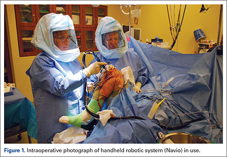
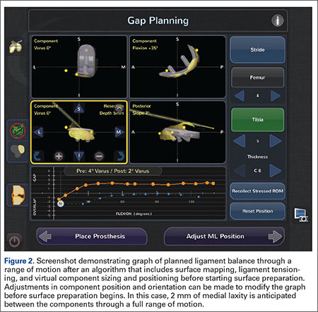
Each robotic-assisted surgery (RAS) system utilizes some sort of 3-dimensional digital map of the surgical surfaces after a process of surface mapping and landmark registration.2 In the case of Mako, this planning process also requires a preoperative computed tomography (CT) scan. Over the past few years, the requirement of a CT scan has proven problematic and costly, as increasingly third-party payers and insurers are denying coverage for additional studies used for preoperative planning, leaving the burden of cost on the patients and/or hospitals. Additionally, in an era in which bundled payment arrangements are commonplace or in which providers are held accountable for costly care, the use of costly preoperative imaging is untenable. Furthermore, there is a growing concern regarding the risk of radiation exposure from CT scans that makes image-free technologies, such as Navio, an alternative for stakeholders.40
At this time, the 2 semiautonomous systems in use for UKA employ different methods to safeguard against inadvertent bone preparation: one by providing haptic constraint beyond which movement of the bur is limited (Mako); the other by modulating the exposure or speed of the handheld robotic bur (Navio) (Figure 3).
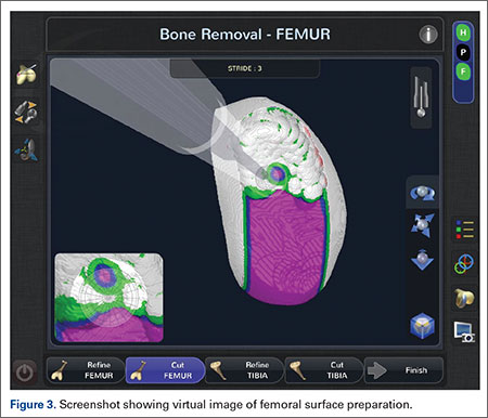
Outcomes of RAS in UKA
Compared to conventional UKA, robotic assistance has consistently demonstrated improved surgical accuracy, even through minimally invasive incisions (Figures 4, 5).6,20-28 Several studies have found substantial reduction in variability and error of component positioning with use of semiautonomous robotic tools.6,21,25 In fact, precision appears to be comparable regardless of whether an image-free system or one requiring a preoperative CT scan is used (Table). Further, in addition to improving component and limb alignment, Plate and colleagues22 demonstrated that RAS-based UKA systems can help the surgeon precisely reproduce plans for soft-tissue balancing. The authors reported ligament balancing to be accurate up to .53 mm compared to the preoperative plan, with approximately 83% of cases balanced within 1 mm of the plan through a full range of flexion.22
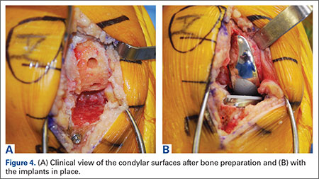
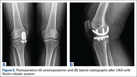
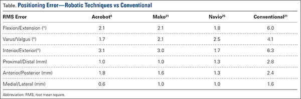
When evaluating advanced and novel technologies, there is undoubtedly concern that there will be increased operative time and a substantial learning curve with those technologies. Karia and colleagues30 found that when inexperienced surgeons performed UKA on synthetic bone models using robotics, the mean compound rotational and translational errors were lower than when conventional techniques were used. Among those using conventional techniques, although surgical times improved during the learning period, positional inaccuracies persisted. On the other hand, robotic assistance enabled surgeons to achieve precision and accuracy when positioning UKA components irrespective of their learning experience.30 Another study, by Coon,31 similarly suggested a shorter learning curve and greater accuracy with RAS using the Mako system compared to conventional techniques. A prospective, multicenter, observational study evaluated the operative times of 11 surgeons during their initial clinical cases using Navio robotic technology for medial UKA after a period of training using cadaver knees and sawbones.41 The learning curve for total surgical time (tracker placement to implant trial phase) indicates that it takes 8 cases to achieve 95% of total learning and maintain a steady state surgical time.
Potential Disadvantages of RAS in UKA
RAS for UKA has several potential disadvantages that must be weighed against their potential benefits. One major barrier to broader use of RAS is the increased cost associated with the technologies.17,19,27,32 Capital and maintenance costs for these systems can be high, and those that require additional advanced imaging, such as CT scans, further challenge the return on investment.17,19,32 In a Markov analysis of one robotic system (Mako), Moschetti and colleagues17 found that if one assumes a system cost of $1.362 million, value can be attained due to slightly better outcomes despite being more expensive than traditional methods. Nonetheless, their analysis of the Mako system estimated that each robot-assisted UKA case cost $19,219, compared to $16,476 with traditional UKA, and was associated with an incremental cost of $47,180 per quality-adjusted life-year. Their analysis further demonstrated that the cost-effectiveness was very sensitive to case volume, with lower costs realized once volumes surpassed 94 cases per year. On the other hand, costs (and thus value) will also obviously vary depending on the capital costs, annual service charges, and avoidance of unnecessary preoperative scans.19 For instance, assuming a cost of $500,000 for the image-free Navio robotic system, return on investment is achievable within 25 cases annually, roughly one-quarter of the cases necessary with the image-based system.
Another disadvantage of RAS systems in UKA is the unique complications associated with their use. Both RAS and conventional UKA can be complicated by similar problems such as component loosening, polyethylene wear, progressive arthritis, infection, stiffness, instability, and thromboembolism. RAS systems, however, carry the additional risk of specific robot-related issues.19,27 Perhaps most notably, the pin tracts for the required optical tracking arrays can create a stress riser in the cortical bone,19,27,33,42 highlighting the importance of inserting these pins in metaphyseal, and not diaphyseal, bone. Soft tissue complications have been reported during bone preparation with autonomous systems in total knee and hip arthroplasty;37,38 however, the senior author (JHL) has not observed that in 1000 consecutive cases with either semiautonomous surgeon-driven robotic tool.19
Finally, systems that require a preoperative CT scan pose an increased radiation risk.40 Ponzio and Lonner40 recently reported that each preoperative CT scan for robotic-assisted knee arthroplasty (using a Mako protocol) is associated with a mean effective dose of radiation of 4.8 mSv, which is approximately equivalent to 48 chest radiographs.34 Further, in that study, at least 25% of patients had been subjected to multiple scans, with some being exposed to cumulative effective doses of up to 103 mSv. This risk should not be considered completely negligible given that 10 mSv may be associated with an increase in the possibility of fatal cancer, and an estimated 29,000 excess cancer cases in the United States annually are reportedly caused by CT scans.40,43,44 However, this increased radiation risk is not inherent to all RAS systems. Image-free systems, such as Navio, do not require CT scans and are thus not associated with this potential disadvantage.
Conclusion
Robotics has come a long way from its humble conceptual beginnings nearly a century ago. Rapid advances in medical technology over the past 10 years have led to the development and growing popularity of RAS in orthopedic surgery, particularly during UKA. Component placement, quantified soft tissue balance, and radiographic alignment appear to be improved and the incidence of outliers reduced with the use of RAS during UKA. Further assessment is needed to determine whether the improved alignment and balance will impact clinical function and/or durability. Early results are very promising, though, creating optimism that the full benefits of RAS in UKA will be further confirmed with additional time and research.
1. Hockstein NG, Gourin CG, Faust RA, Terris DJ. A history of robots: from science fiction to surgical robotics. J Robot Surg. 2007;1(2):113-118.
2. Tamam C, Poehling GG. Robotic-assisted unicompartmental knee arthroplasty. Sports Med Arthrosc. 2014;22(4):219-222.
3. Beasley RA. Medical robots: current systems and research directions. Journal of Robotics. 2012. doi:10.1155/2012/401613.
4. Bargar WL. Robots in orthopaedic surgery: past, present, and future. Clin Orthop Relat Res. 2007;463:31-36.
5. Matsen FA 3rd, Garbini JL, Sidles JA, Pratt B, Baumgarten D, Kaiura R. Robotic assistance in orthopaedic surgery. A proof of principle using distal femoral arthroplasty. Clin Orthop Relat Res. 1993;(296):178-186.
6. Cobb J, Henckel J, Gomes P, et al. Hands-on robotic unicompartmental knee replacement: a prospective, randomised controlled study of the acrobot system. J Bone Joint Surg Br. 2006;88(2):188-197.
7. Borus T, Thornhill T. Unicompartmental knee arthroplasty.
J Am Acad Orthop Surg. 2008;16(1):9-18.
8. Berger RA, Meneghini RM, Jacobs JJ, et al. Results of unicompartmental knee arthroplasty at a minimum of ten years of follow-up. J Bone Joint Surg Am. 2005;87(5):999-1006.
9. Price AJ, Waite JC, Svard U. Long-term clinical results of the medial Oxford unicompartmental knee arthroplasty. Clin Orthop Relat Res. 2005;(435):171-180.
10. Collier MB, Eickmann TH, Sukezaki F, McAuley JP, Engh GA. Patient, implant, and alignment factors associated with revision of medial compartment unicondylar arthroplasty. J Arthroplasty. 2006;21(6 Suppl 2):108-115.
11. Hamilton WG, Collier MB, Tarabee E, McAuley JP, Engh CA Jr, Engh GA. Incidence and reasons for reoperation after minimally invasive unicompartmental knee arthroplasty. J Arthroplasty. 2006;21(6 Suppl 2):98-107.
12. Hernigou P, Deschamps G. Alignment influences wear in the knee after medial unicompartmental arthroplasty. Clin Orthop Relat Res. 2004;(423):161-165.
13. Hernigou P, Deschamps G. Posterior slope of the tibial implant and the outcome of unicompartmental knee arthroplasty. J Bone Joint Surg Am. 2004;86-A(3):506-511.
14. Lonner JH. Indications for unicompartmental knee arthroplasty and rationale for robotic arm-assisted technology. Am J Orthop. 2009;38(2 Suppl):3-6.
15. Lonner JH. Robotically-assisted unicompartmental knee arthroplasty with a hand-held image-free sculpting tool. Orthop Clin North Am. 2016;47(1):29-40.
16. Orthopedic Network News. 2013 Hip and Knee Implant Review. http://www.OrthopedicNetworkNews.com. Published July 2013. Accessed March 7, 2016.
17. Moschetti WE, Konopka JF, Rubash HE, Genuario JW. Can robot-assisted unicompartmental knee arthroplasty be cost-effective? A Markov decision analysis. J Arthroplasty. 2016;31(4):759-765.
18. Roche M. Robotic-assisted unicompartmental knee arthroplasty: the MAKO experience. Orthop Clin North Am. 2015;46(1):125-131.
19. Lonner JH. Robotically assisted unicompartmental knee arthroplasty with a handheld image-free sculpting tool. Oper Tech Orthop. 2015;25:104-113.
20. Mofidi A, Plate JF, Lu B, et al. Assessment of accuracy of robotically assisted unicompartmental arthroplasty. Knee Surg Sports Traumatol Arthrosc. 2014;22(8):1918-1925.
21. Dunbar NJ, Roche MW, Park BH, Branch SH, Conditt MA, Banks SA. Accuracy of dynamic tactile-guided unicompartmental knee arthroplasty. J Arthroplasty. 2012;27(5):803-808.e1.
22. Plate JF, Mofidi A, Mannava S, et al. Achieving accurate ligament balancing using robotic-assisted unicompartmental knee arthroplasty. Adv Orthop. 2013;2013:837167.
23. Smith JR, Riches PE, Rowe PJ. Accuracy of a freehand sculpting tool for unicondylar knee replacement. Int J Med Robot. 2014;10(2):162-169.
24. Smith JR, Picard F, Lonner J, et al. The accuracy of a robotically-controlled freehand sculpting tool for unicondylar knee arthroplasty. J Bone Joint Surg Br. 2014;96-B(Suppl 16):12.
25. Lonner JH, Smith JR, Picard F, Hamlin B, Rowe PJ, Riches PE. High degree of accuracy of a novel image-free handheld robot for unicondylar knee arthroplasty in a cadaveric study. Clin Orthop Relat Res. 2015;473(1):206-212.
26. Lonner JH, John TK, Conditt MA. Robotic arm-assisted UKA improves tibial component alignment: a pilot study. Clin Orthop Relat Res. 2010;468(1):141-146.
27. Sinha RK. Outcomes of robotic arm-assisted unicompartmental knee arthroplasty. Am J Orthop. 2009;38(2 Suppl):20-22.
28. Pearle AD, O’Loughlin PF, Kendoff DO. Robot-assisted unicompartmental knee arthroplasty. J Arthroplasty. 2010;25(2):230-237.
29. Mozes A, Chang TC, Arata L, Zhao W. Three-dimensional A-mode ultrasound calibration and registration for robotic orthopaedic knee surgery. Int J Med Robot. 2010;6(1):91-101.
30. Karia M, Masjedi M, Andrews B, Jaffry Z, Cobb J. Robotic assistance enables inexperienced surgeons to perform unicompartmental knee arthroplasties on dry bone models with accuracy superior to conventional methods. Adv Orthop. 2013;2013:481039.
31. Coon TM. Integrating robotic technology into the operating room. Am J Orthop. 2009;38(2 Suppl):7-9.
32. Swank ML, Alkire M, Conditt M, Lonner JH. Technology and cost-effectiveness in knee arthroplasty: computer navigation and robotics. Am J Orthop. 2009;38(2 Suppl):32-36.
33. Roche M, Augustin D, Conditt M. One year outcomes of robotically guided UKA. In: Proceedings of the 21st Annual Congress of the International Society of Technology in Arthroplasty. Sacramento, CA: International Society for Technology in Arthroplasty; 2008:175.
34. Dalton DM, Burke TP, Kelly EG, Curtin PD. Quantitative analysis of technological innovation in knee arthroplasty: using patent and publication metrics to identify developments and trends. J Arthroplasty. 2015. [Epub ahead of print]
35. Lonner JH. Modular bicompartmental knee arthroplasty with robotic arm assistance. Am J Orthop. 2009;38(2 Suppl):28-31.
36. Kamath AF, Levack A, John T, Thomas BS, Lonner JH. Minimum two-year outcomes of modular bicompartmental knee arthroplasty. J Arthroplasty. 2014;29(1):75-79.
37. Song EK, Seon JK, Yim JH, Netravali NA, Bargar WL. Robotic-assisted TKA reduces postoperative alignment outliers and improves gap balance compared to conventional TKA. Clin Orthop Relat Res. 2013;471(1):118-126.
38. Chun YS, Kim KI, Cho YJ, Kim YH, Yoo MC, Rhyu KH. Causes and patterns of aborting a robot-assisted arthroplasty. J Arthroplasty. 2011;26(4):621-625.
39. MAKO Surgical Corp. Fact Sheet. http://www.makosurgical.com/assets/files/Company/newsroom/Corporate_Fact_Sheet_208578r00.pdf. Published 2013. Accessed March 7, 2016.
40. Ponzio DY, Lonner JH. Preoperative mapping in unicompartmental knee arthroplasty using computed tomography scans is associated with radiation exposure and carries high cost. J Arthroplasty. 2015;30(6):964-967.
41. Wallace D, Gregori A, Picard F, et al. The learning curve of a novel handheld robotic system for unicondylar knee arthroplasty. Paper presented at: 14th Annual Meeting of the International Society for Computer Assisted Orthopaedic Surgery. June 18-21, 2014; Milan, Italy.
42. Wysocki RW, Sheinkop MB, Virkus WW, Della Valle CJ. Femoral fracture through a previous pin site after computer-assisted total knee arthroplasty. J Arthroplasty. 2008;23(3):462-465.
43. Costello JE, Cecava ND, Tucker JE, Bau JL. CT radiation dose: current controversies and dose reduction strategies. AJR Am J Roentgenol. 2013;201(6):1283-1290.
44. Berrington de González A, Mahesh M, Kim KP, et al. Projected cancer risks from computed tomographic scans performed in the United States in 2007. Arch Intern Med. 2009;169(22):2071-2077.
The concept of robotics is relatively new in medical practice. The term “robot” itself is less than 100 years old, having been first introduced to popular culture in 1917 by Joseph Capek in the science fiction story Opilec.1,2 Robots eventually transitioned from this initial fictional literary setting to reality in 1958, when General Motors began adding automated machines to its assembly lines.1 However, it was not until the 1980s that robotics and their exacting efficiencies would be introduced in the medical field, and it would take another decade before they would enter the specialty of orthopedics.1-4
The first robotic-assisted orthopedic surgery was reportedly performed in 1992, when the Robodoc autonomous system was utilized for total hip arthroplasty.2-4 A robotic system for total knee arthroplasty (TKA) was first described in 1993, but it would take several more years until a system for unicompartmental knee arthroplasty (UKA) would be commercialized and used clinically.5,6 The rationale for advancement of robotic technology for isolated medial or lateral knee arthritis stems from the recognition that while UKA is effective and durable when components and limb are well aligned and soft tissues appropriately balanced, they are less forgiving of even slight component malalignment of as little as 2° to 3° and prone to premature loosening or wear in those circumstances.7-13,14 In the mid 2000s, Cobb and colleagues6 reported using a semiautonomous robot for UKA. Since then, emergence of other semiautonomous robotic systems has led to greater market penetration and technology utilization.15
Currently, an estimated 15% to 20% of UKA surgeries are being performed with robotic assistance.16 Further, patent activity and peer-reviewed publications related to robotic technology in UKA (which can be considered surrogate measures of interest and evolving development and experience with robotic technologies) have increased dramatically over the past few years.2,6,14,17,18-34 To date, while the most dramatic growth of robotic utilization and case volumes has occurred in the subspecialty of UKA, semiautonomous robotic systems have been used with increasing frequency for patellofemoral and bicompartmental knee arthroplasty.35,36 Robotics have been used sparingly for TKA, and limited to autonomous systems;37,38 however, it is anticipated that emergence of semiautonomous platforms for TKA will further expand the role of robotics over the next decade, particularly as our focus shifts beyond component and limb alignment in TKA and more towards the role of robotics in soft tissue balancing, reduction in instrumentation and inventory and its attendant cost savings, and surgical efficiencies. One semiautonomous robotic technology first used in 2006 (Mako, Stryker) reported a 130% increase in robotic volume from 2011 to 2012; another, first used in 2013, reported growth of 480% between 2013 and 2014, due to its improved cost structure, ease of use, smaller footprint, image-free platform and applicability in ambulatory surgery centers (Navio, Smith & Nephew; data supplied by manufacturer), demonstrating the growing popularity of robotic technology.17,39 Further, a recent analysis of potential market penetration over the next decade published by Medical Device and Diagnostic Industry (http://www.mddionline.com) projected that nearly 37% of UKAs and 23% of TKAs will be performed with robotics in 10 years.
Distinction Between Robotic-Assisted Technologies
Autonomous systems involve pre-programming the system with parameters that define the amount and orientation of bone to be removed, after which the system prepares the surfaces independent of surgeon control, other than having access to a “shutdown” switch. There are currently no autonomous robotic tools approved by the US Food and Drug Administration (FDA) for knee arthroplasty.
Semiautonomous systems involve the mapping of condylar landmarks and determination of alignment indices, which also defines the volume and orientation of bone to be removed. While the systems remove bone and cartilage within the pre-established parameters, the robotic tools are controlled and manipulated by the surgeon (Figure 1). The predetermined safe zones modulate and safeguard the surgical actions. These systems also provide real-time quantification of soft tissue balancing, which may contribute to the reported successful clinical and functional outcomes with semiautonomous systems (Figure 2).2,4,19,22 There are several semiautonomous robotic systems that are approved for use by the FDA.
Each robotic-assisted surgery (RAS) system utilizes some sort of 3-dimensional digital map of the surgical surfaces after a process of surface mapping and landmark registration.2 In the case of Mako, this planning process also requires a preoperative computed tomography (CT) scan. Over the past few years, the requirement of a CT scan has proven problematic and costly, as increasingly third-party payers and insurers are denying coverage for additional studies used for preoperative planning, leaving the burden of cost on the patients and/or hospitals. Additionally, in an era in which bundled payment arrangements are commonplace or in which providers are held accountable for costly care, the use of costly preoperative imaging is untenable. Furthermore, there is a growing concern regarding the risk of radiation exposure from CT scans that makes image-free technologies, such as Navio, an alternative for stakeholders.40
At this time, the 2 semiautonomous systems in use for UKA employ different methods to safeguard against inadvertent bone preparation: one by providing haptic constraint beyond which movement of the bur is limited (Mako); the other by modulating the exposure or speed of the handheld robotic bur (Navio) (Figure 3).
Outcomes of RAS in UKA
Compared to conventional UKA, robotic assistance has consistently demonstrated improved surgical accuracy, even through minimally invasive incisions (Figures 4, 5).6,20-28 Several studies have found substantial reduction in variability and error of component positioning with use of semiautonomous robotic tools.6,21,25 In fact, precision appears to be comparable regardless of whether an image-free system or one requiring a preoperative CT scan is used (Table). Further, in addition to improving component and limb alignment, Plate and colleagues22 demonstrated that RAS-based UKA systems can help the surgeon precisely reproduce plans for soft-tissue balancing. The authors reported ligament balancing to be accurate up to .53 mm compared to the preoperative plan, with approximately 83% of cases balanced within 1 mm of the plan through a full range of flexion.22
When evaluating advanced and novel technologies, there is undoubtedly concern that there will be increased operative time and a substantial learning curve with those technologies. Karia and colleagues30 found that when inexperienced surgeons performed UKA on synthetic bone models using robotics, the mean compound rotational and translational errors were lower than when conventional techniques were used. Among those using conventional techniques, although surgical times improved during the learning period, positional inaccuracies persisted. On the other hand, robotic assistance enabled surgeons to achieve precision and accuracy when positioning UKA components irrespective of their learning experience.30 Another study, by Coon,31 similarly suggested a shorter learning curve and greater accuracy with RAS using the Mako system compared to conventional techniques. A prospective, multicenter, observational study evaluated the operative times of 11 surgeons during their initial clinical cases using Navio robotic technology for medial UKA after a period of training using cadaver knees and sawbones.41 The learning curve for total surgical time (tracker placement to implant trial phase) indicates that it takes 8 cases to achieve 95% of total learning and maintain a steady state surgical time.
Potential Disadvantages of RAS in UKA
RAS for UKA has several potential disadvantages that must be weighed against their potential benefits. One major barrier to broader use of RAS is the increased cost associated with the technologies.17,19,27,32 Capital and maintenance costs for these systems can be high, and those that require additional advanced imaging, such as CT scans, further challenge the return on investment.17,19,32 In a Markov analysis of one robotic system (Mako), Moschetti and colleagues17 found that if one assumes a system cost of $1.362 million, value can be attained due to slightly better outcomes despite being more expensive than traditional methods. Nonetheless, their analysis of the Mako system estimated that each robot-assisted UKA case cost $19,219, compared to $16,476 with traditional UKA, and was associated with an incremental cost of $47,180 per quality-adjusted life-year. Their analysis further demonstrated that the cost-effectiveness was very sensitive to case volume, with lower costs realized once volumes surpassed 94 cases per year. On the other hand, costs (and thus value) will also obviously vary depending on the capital costs, annual service charges, and avoidance of unnecessary preoperative scans.19 For instance, assuming a cost of $500,000 for the image-free Navio robotic system, return on investment is achievable within 25 cases annually, roughly one-quarter of the cases necessary with the image-based system.
Another disadvantage of RAS systems in UKA is the unique complications associated with their use. Both RAS and conventional UKA can be complicated by similar problems such as component loosening, polyethylene wear, progressive arthritis, infection, stiffness, instability, and thromboembolism. RAS systems, however, carry the additional risk of specific robot-related issues.19,27 Perhaps most notably, the pin tracts for the required optical tracking arrays can create a stress riser in the cortical bone,19,27,33,42 highlighting the importance of inserting these pins in metaphyseal, and not diaphyseal, bone. Soft tissue complications have been reported during bone preparation with autonomous systems in total knee and hip arthroplasty;37,38 however, the senior author (JHL) has not observed that in 1000 consecutive cases with either semiautonomous surgeon-driven robotic tool.19
Finally, systems that require a preoperative CT scan pose an increased radiation risk.40 Ponzio and Lonner40 recently reported that each preoperative CT scan for robotic-assisted knee arthroplasty (using a Mako protocol) is associated with a mean effective dose of radiation of 4.8 mSv, which is approximately equivalent to 48 chest radiographs.34 Further, in that study, at least 25% of patients had been subjected to multiple scans, with some being exposed to cumulative effective doses of up to 103 mSv. This risk should not be considered completely negligible given that 10 mSv may be associated with an increase in the possibility of fatal cancer, and an estimated 29,000 excess cancer cases in the United States annually are reportedly caused by CT scans.40,43,44 However, this increased radiation risk is not inherent to all RAS systems. Image-free systems, such as Navio, do not require CT scans and are thus not associated with this potential disadvantage.
Conclusion
Robotics has come a long way from its humble conceptual beginnings nearly a century ago. Rapid advances in medical technology over the past 10 years have led to the development and growing popularity of RAS in orthopedic surgery, particularly during UKA. Component placement, quantified soft tissue balance, and radiographic alignment appear to be improved and the incidence of outliers reduced with the use of RAS during UKA. Further assessment is needed to determine whether the improved alignment and balance will impact clinical function and/or durability. Early results are very promising, though, creating optimism that the full benefits of RAS in UKA will be further confirmed with additional time and research.
1. Hockstein NG, Gourin CG, Faust RA, Terris DJ. A history of robots: from science fiction to surgical robotics. J Robot Surg. 2007;1(2):113-118.
2. Tamam C, Poehling GG. Robotic-assisted unicompartmental knee arthroplasty. Sports Med Arthrosc. 2014;22(4):219-222.
3. Beasley RA. Medical robots: current systems and research directions. Journal of Robotics. 2012. doi:10.1155/2012/401613.
4. Bargar WL. Robots in orthopaedic surgery: past, present, and future. Clin Orthop Relat Res. 2007;463:31-36.
5. Matsen FA 3rd, Garbini JL, Sidles JA, Pratt B, Baumgarten D, Kaiura R. Robotic assistance in orthopaedic surgery. A proof of principle using distal femoral arthroplasty. Clin Orthop Relat Res. 1993;(296):178-186.
6. Cobb J, Henckel J, Gomes P, et al. Hands-on robotic unicompartmental knee replacement: a prospective, randomised controlled study of the acrobot system. J Bone Joint Surg Br. 2006;88(2):188-197.
7. Borus T, Thornhill T. Unicompartmental knee arthroplasty.
J Am Acad Orthop Surg. 2008;16(1):9-18.
8. Berger RA, Meneghini RM, Jacobs JJ, et al. Results of unicompartmental knee arthroplasty at a minimum of ten years of follow-up. J Bone Joint Surg Am. 2005;87(5):999-1006.
9. Price AJ, Waite JC, Svard U. Long-term clinical results of the medial Oxford unicompartmental knee arthroplasty. Clin Orthop Relat Res. 2005;(435):171-180.
10. Collier MB, Eickmann TH, Sukezaki F, McAuley JP, Engh GA. Patient, implant, and alignment factors associated with revision of medial compartment unicondylar arthroplasty. J Arthroplasty. 2006;21(6 Suppl 2):108-115.
11. Hamilton WG, Collier MB, Tarabee E, McAuley JP, Engh CA Jr, Engh GA. Incidence and reasons for reoperation after minimally invasive unicompartmental knee arthroplasty. J Arthroplasty. 2006;21(6 Suppl 2):98-107.
12. Hernigou P, Deschamps G. Alignment influences wear in the knee after medial unicompartmental arthroplasty. Clin Orthop Relat Res. 2004;(423):161-165.
13. Hernigou P, Deschamps G. Posterior slope of the tibial implant and the outcome of unicompartmental knee arthroplasty. J Bone Joint Surg Am. 2004;86-A(3):506-511.
14. Lonner JH. Indications for unicompartmental knee arthroplasty and rationale for robotic arm-assisted technology. Am J Orthop. 2009;38(2 Suppl):3-6.
15. Lonner JH. Robotically-assisted unicompartmental knee arthroplasty with a hand-held image-free sculpting tool. Orthop Clin North Am. 2016;47(1):29-40.
16. Orthopedic Network News. 2013 Hip and Knee Implant Review. http://www.OrthopedicNetworkNews.com. Published July 2013. Accessed March 7, 2016.
17. Moschetti WE, Konopka JF, Rubash HE, Genuario JW. Can robot-assisted unicompartmental knee arthroplasty be cost-effective? A Markov decision analysis. J Arthroplasty. 2016;31(4):759-765.
18. Roche M. Robotic-assisted unicompartmental knee arthroplasty: the MAKO experience. Orthop Clin North Am. 2015;46(1):125-131.
19. Lonner JH. Robotically assisted unicompartmental knee arthroplasty with a handheld image-free sculpting tool. Oper Tech Orthop. 2015;25:104-113.
20. Mofidi A, Plate JF, Lu B, et al. Assessment of accuracy of robotically assisted unicompartmental arthroplasty. Knee Surg Sports Traumatol Arthrosc. 2014;22(8):1918-1925.
21. Dunbar NJ, Roche MW, Park BH, Branch SH, Conditt MA, Banks SA. Accuracy of dynamic tactile-guided unicompartmental knee arthroplasty. J Arthroplasty. 2012;27(5):803-808.e1.
22. Plate JF, Mofidi A, Mannava S, et al. Achieving accurate ligament balancing using robotic-assisted unicompartmental knee arthroplasty. Adv Orthop. 2013;2013:837167.
23. Smith JR, Riches PE, Rowe PJ. Accuracy of a freehand sculpting tool for unicondylar knee replacement. Int J Med Robot. 2014;10(2):162-169.
24. Smith JR, Picard F, Lonner J, et al. The accuracy of a robotically-controlled freehand sculpting tool for unicondylar knee arthroplasty. J Bone Joint Surg Br. 2014;96-B(Suppl 16):12.
25. Lonner JH, Smith JR, Picard F, Hamlin B, Rowe PJ, Riches PE. High degree of accuracy of a novel image-free handheld robot for unicondylar knee arthroplasty in a cadaveric study. Clin Orthop Relat Res. 2015;473(1):206-212.
26. Lonner JH, John TK, Conditt MA. Robotic arm-assisted UKA improves tibial component alignment: a pilot study. Clin Orthop Relat Res. 2010;468(1):141-146.
27. Sinha RK. Outcomes of robotic arm-assisted unicompartmental knee arthroplasty. Am J Orthop. 2009;38(2 Suppl):20-22.
28. Pearle AD, O’Loughlin PF, Kendoff DO. Robot-assisted unicompartmental knee arthroplasty. J Arthroplasty. 2010;25(2):230-237.
29. Mozes A, Chang TC, Arata L, Zhao W. Three-dimensional A-mode ultrasound calibration and registration for robotic orthopaedic knee surgery. Int J Med Robot. 2010;6(1):91-101.
30. Karia M, Masjedi M, Andrews B, Jaffry Z, Cobb J. Robotic assistance enables inexperienced surgeons to perform unicompartmental knee arthroplasties on dry bone models with accuracy superior to conventional methods. Adv Orthop. 2013;2013:481039.
31. Coon TM. Integrating robotic technology into the operating room. Am J Orthop. 2009;38(2 Suppl):7-9.
32. Swank ML, Alkire M, Conditt M, Lonner JH. Technology and cost-effectiveness in knee arthroplasty: computer navigation and robotics. Am J Orthop. 2009;38(2 Suppl):32-36.
33. Roche M, Augustin D, Conditt M. One year outcomes of robotically guided UKA. In: Proceedings of the 21st Annual Congress of the International Society of Technology in Arthroplasty. Sacramento, CA: International Society for Technology in Arthroplasty; 2008:175.
34. Dalton DM, Burke TP, Kelly EG, Curtin PD. Quantitative analysis of technological innovation in knee arthroplasty: using patent and publication metrics to identify developments and trends. J Arthroplasty. 2015. [Epub ahead of print]
35. Lonner JH. Modular bicompartmental knee arthroplasty with robotic arm assistance. Am J Orthop. 2009;38(2 Suppl):28-31.
36. Kamath AF, Levack A, John T, Thomas BS, Lonner JH. Minimum two-year outcomes of modular bicompartmental knee arthroplasty. J Arthroplasty. 2014;29(1):75-79.
37. Song EK, Seon JK, Yim JH, Netravali NA, Bargar WL. Robotic-assisted TKA reduces postoperative alignment outliers and improves gap balance compared to conventional TKA. Clin Orthop Relat Res. 2013;471(1):118-126.
38. Chun YS, Kim KI, Cho YJ, Kim YH, Yoo MC, Rhyu KH. Causes and patterns of aborting a robot-assisted arthroplasty. J Arthroplasty. 2011;26(4):621-625.
39. MAKO Surgical Corp. Fact Sheet. http://www.makosurgical.com/assets/files/Company/newsroom/Corporate_Fact_Sheet_208578r00.pdf. Published 2013. Accessed March 7, 2016.
40. Ponzio DY, Lonner JH. Preoperative mapping in unicompartmental knee arthroplasty using computed tomography scans is associated with radiation exposure and carries high cost. J Arthroplasty. 2015;30(6):964-967.
41. Wallace D, Gregori A, Picard F, et al. The learning curve of a novel handheld robotic system for unicondylar knee arthroplasty. Paper presented at: 14th Annual Meeting of the International Society for Computer Assisted Orthopaedic Surgery. June 18-21, 2014; Milan, Italy.
42. Wysocki RW, Sheinkop MB, Virkus WW, Della Valle CJ. Femoral fracture through a previous pin site after computer-assisted total knee arthroplasty. J Arthroplasty. 2008;23(3):462-465.
43. Costello JE, Cecava ND, Tucker JE, Bau JL. CT radiation dose: current controversies and dose reduction strategies. AJR Am J Roentgenol. 2013;201(6):1283-1290.
44. Berrington de González A, Mahesh M, Kim KP, et al. Projected cancer risks from computed tomographic scans performed in the United States in 2007. Arch Intern Med. 2009;169(22):2071-2077.
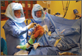
Investigational HBV core inhibitor shows early clinical promise
BARCELONA – An investigational drug that targets the hepatitis B virus (HBV) core protein is a “totally new approach” to treating chronic HBV infection according to the results of an early-phase clinical study.
In an ongoing, international, phase I study presented during the late-breaker session at the International Liver Congress, 4 weeks of treatment with NVR 3-778 was well tolerated and did not result in any drug discontinuations in chronically infected patients. There were dose-related reductions in HBV DNA and early reductions in HBeAg were observed.

“NVR 3-778 is a first-in-class HBV core inhibitor,” study investigator Dr. Man-Fung Yuen, Queen Mary Hospital, Hong Kong, said at a press briefing held at the meeting, which is sponsored by the European Association for the Study of the Liver (EASL). “The HBV core protein has many functions and is responsible for the most important pathway of the virus’ replication – nucleocapsid formation,” he explained.
The rationale behind its development is that although there are effective treatments such as nucleoside and nucleotide analogs (NAs) and pegylated interferon (peg-IFN) that can suppress the activity of HBV for many years and thus slow down damage to the liver, it is unusual to clear the virus permanently. Furthermore, as most patients require potentially life-long treatment, issues such as long-term safety, patients’ adherence, resistance, and cost of therapy come into play.
Dr. Yuen observed that achieving durable responses in patients with chronic HBV is likely to require combinations of potential agents, probably with complementary modes of action.
Preclinical data have shown that NVR 3-778 induces the rapid assembly of nonfunctional capsids and that it inhibits viral replication in a humanized mouse hepatocyte cell model. It has also been shown to reduce HBV DNA to a comparable extent as entecavir when used alone in a mouse model, with undetectable levels reached when used in combination with peg-IFN alpha-2a.
Dr. Yuen reported the preliminary results from the second part of the phase I study in 64 adults with chronic HBV, noting that the first part of the study in healthy volunteers had been completed successfully.
The aim was to examine the safety and efficacy of NVR 3-778 alone and in combination with peg-IFN alpha-2a in previously untreated patients aged between 18 and 65 years who were HBsAg- and HbeAg-positive, had HBV DNA of 20,000 or more copies per IU/mL, with no cirrhosis of the liver, as determined by liver biopsy or imaging.
Patients were randomly assigned to six groups, with four groups receiving the investigational therapy alone at four increasing doses (100, 200, 400, once daily and 600 mg twice daily). There was a staged initiation of each escalating dose of NVR 3-778 used in these groups, with the 100 mg initiated first and if, after 2 weeks, there were no interim safety concerns, the next dose groups, 200 mg, then 400 mg, then 600 mg were started. The other two groups of patients received NVR 3-788 (600 mg) with peg-IFN alpha-2a (180 microg/week) or peg-IFN alpha-2a plus placebo. Treatment for all groups was for 28 days with 28 days of follow-up.
The mean age of patients in each group ranged from 32 to 48 years, with the older patients more likely to be treated with peg-IFN alpha-2a alone or with NVR 3-788. Most of the patients studied were Chinese and the mean baseline HBV DNA was 7.5-8.3 log10 IU/mL.
A total of 98 adverse events were seen in 40 of 64 patients treated, although there was not any trend for more effects with the investigational treatment versus placebo as doses escalated. There were 21 adverse events seen in 20 of 46 patients that were possibly or probably related to the study drug, of which most were grade 1 nausea. Grade 2 nausea occurred only once in a patient given the 100-mg dose. There was one serious adverse event, a grade 3 papulovesicular rash on the hands and feet that occurred in a patient in the 100-mg group, but this responded to therapy. This side effect started about 20 days after treatment and resolved over a period of 7 months.
Although generally mild, more adverse effects were seen in the patients treated with a combination of NVR 3-788 and peg-IFN alpha-2a, which Dr. Yuen noted was thought to be more likely a result of the IFN therapy.
There was not much difference in the mean change in HBV DNA from baseline for the 100-400-mg groups, but there was a 1.72-log10 IU/mL decrease achieved with the 600-mg twice-daily dose. The greatest reduction, however, was seen when NVR 3-788 was combined with peg-IFN alpha-2a, with a 1.97-log10 IU/mL change.
“Encouraging early reductions in HBV RNA and quantitative serum HBeAg were observed,” Dr. Yuen said. He noted that the longer-term safety and efficacy of the novel agent in combination with peg-IFN alpha-2a and first-line HBV NAs will now be further assessed in phase II studies.
“At the moment we do not have a cure for hepatitis B, only treatment,” said Dr. Frank Tacke of the University Hospital Aachen (Germany), who chaired the press briefing where Dr. Yuen first aired the findings. NVR 3-788 represents “a totally new approach to this disease that we hope will lead to a cure,” Dr. Tacke said.
In an EASL-issued press release, Dr. Tacke also noted: “The results from this study are certainly interesting and promising for the treatment of patients with hepatitis B. The medical community is always on the lookout for treatments which can cure this condition, as opposed to simply suppressing the replication of the virus. More research is needed to confirm whether NVR 3-778 could really change the treatment paradigm.”
Novira Therapeutics financed the study. Dr. Yuen has been a consultant, speaker, or both for Arrowhead, Bristol-Myers Squibb, GlaxoSmithKline, Gilead, Novartis, and Roche. Dr. Tacke did not have any relevant disclosures.
BARCELONA – An investigational drug that targets the hepatitis B virus (HBV) core protein is a “totally new approach” to treating chronic HBV infection according to the results of an early-phase clinical study.
In an ongoing, international, phase I study presented during the late-breaker session at the International Liver Congress, 4 weeks of treatment with NVR 3-778 was well tolerated and did not result in any drug discontinuations in chronically infected patients. There were dose-related reductions in HBV DNA and early reductions in HBeAg were observed.
“NVR 3-778 is a first-in-class HBV core inhibitor,” study investigator Dr. Man-Fung Yuen, Queen Mary Hospital, Hong Kong, said at a press briefing held at the meeting, which is sponsored by the European Association for the Study of the Liver (EASL). “The HBV core protein has many functions and is responsible for the most important pathway of the virus’ replication – nucleocapsid formation,” he explained.
The rationale behind its development is that although there are effective treatments such as nucleoside and nucleotide analogs (NAs) and pegylated interferon (peg-IFN) that can suppress the activity of HBV for many years and thus slow down damage to the liver, it is unusual to clear the virus permanently. Furthermore, as most patients require potentially life-long treatment, issues such as long-term safety, patients’ adherence, resistance, and cost of therapy come into play.
Dr. Yuen observed that achieving durable responses in patients with chronic HBV is likely to require combinations of potential agents, probably with complementary modes of action.
Preclinical data have shown that NVR 3-778 induces the rapid assembly of nonfunctional capsids and that it inhibits viral replication in a humanized mouse hepatocyte cell model. It has also been shown to reduce HBV DNA to a comparable extent as entecavir when used alone in a mouse model, with undetectable levels reached when used in combination with peg-IFN alpha-2a.
Dr. Yuen reported the preliminary results from the second part of the phase I study in 64 adults with chronic HBV, noting that the first part of the study in healthy volunteers had been completed successfully.
The aim was to examine the safety and efficacy of NVR 3-778 alone and in combination with peg-IFN alpha-2a in previously untreated patients aged between 18 and 65 years who were HBsAg- and HbeAg-positive, had HBV DNA of 20,000 or more copies per IU/mL, with no cirrhosis of the liver, as determined by liver biopsy or imaging.
Patients were randomly assigned to six groups, with four groups receiving the investigational therapy alone at four increasing doses (100, 200, 400, once daily and 600 mg twice daily). There was a staged initiation of each escalating dose of NVR 3-778 used in these groups, with the 100 mg initiated first and if, after 2 weeks, there were no interim safety concerns, the next dose groups, 200 mg, then 400 mg, then 600 mg were started. The other two groups of patients received NVR 3-788 (600 mg) with peg-IFN alpha-2a (180 microg/week) or peg-IFN alpha-2a plus placebo. Treatment for all groups was for 28 days with 28 days of follow-up.
The mean age of patients in each group ranged from 32 to 48 years, with the older patients more likely to be treated with peg-IFN alpha-2a alone or with NVR 3-788. Most of the patients studied were Chinese and the mean baseline HBV DNA was 7.5-8.3 log10 IU/mL.
A total of 98 adverse events were seen in 40 of 64 patients treated, although there was not any trend for more effects with the investigational treatment versus placebo as doses escalated. There were 21 adverse events seen in 20 of 46 patients that were possibly or probably related to the study drug, of which most were grade 1 nausea. Grade 2 nausea occurred only once in a patient given the 100-mg dose. There was one serious adverse event, a grade 3 papulovesicular rash on the hands and feet that occurred in a patient in the 100-mg group, but this responded to therapy. This side effect started about 20 days after treatment and resolved over a period of 7 months.
Although generally mild, more adverse effects were seen in the patients treated with a combination of NVR 3-788 and peg-IFN alpha-2a, which Dr. Yuen noted was thought to be more likely a result of the IFN therapy.
There was not much difference in the mean change in HBV DNA from baseline for the 100-400-mg groups, but there was a 1.72-log10 IU/mL decrease achieved with the 600-mg twice-daily dose. The greatest reduction, however, was seen when NVR 3-788 was combined with peg-IFN alpha-2a, with a 1.97-log10 IU/mL change.
“Encouraging early reductions in HBV RNA and quantitative serum HBeAg were observed,” Dr. Yuen said. He noted that the longer-term safety and efficacy of the novel agent in combination with peg-IFN alpha-2a and first-line HBV NAs will now be further assessed in phase II studies.
“At the moment we do not have a cure for hepatitis B, only treatment,” said Dr. Frank Tacke of the University Hospital Aachen (Germany), who chaired the press briefing where Dr. Yuen first aired the findings. NVR 3-788 represents “a totally new approach to this disease that we hope will lead to a cure,” Dr. Tacke said.
In an EASL-issued press release, Dr. Tacke also noted: “The results from this study are certainly interesting and promising for the treatment of patients with hepatitis B. The medical community is always on the lookout for treatments which can cure this condition, as opposed to simply suppressing the replication of the virus. More research is needed to confirm whether NVR 3-778 could really change the treatment paradigm.”
Novira Therapeutics financed the study. Dr. Yuen has been a consultant, speaker, or both for Arrowhead, Bristol-Myers Squibb, GlaxoSmithKline, Gilead, Novartis, and Roche. Dr. Tacke did not have any relevant disclosures.
AT THE INTERNATIONAL LIVER CONGRESS 2016
Key clinical point: NVR 3-778 is a “first-in-class” HBV core inhibitor in early clinical development showing promising results.
Major finding: There were no safety concerns. HBV DNA decreased by a respective 1.72 and 1.97 log10 IU/mL from baseline with a 600-mg twice-daily dose alone or in combination with peg-IFN alpha-2a.
Data source: Phase Ib study of 64 patients with chronic HBV infection treated with escalating doses of NVR 3-788.
Disclosures: Novira Therapeutics financed the study. Dr. Yuen has been a consultant, speaker, or both for Arrowhead, Bristol-Myers Squibb, GlaxoSmithKline, Gilead, Novartis, and Roche. Dr. Tacke did not have any relevant disclosures.
After Inflectra’s approval, challenges remain for biosimilars
Now that the Food and Drug Administration has approved Inflectra as the first biosimilar version of the anti–tumor necrosis factor-alpha agent Remicade, rheumatologists and patient advocacy groups are taking stock of how it may be used in practice, and what the future holds for biosimilar drugs, with so many questions still unanswered regarding price, substitution, and safety.

Inflectra, approved in early April and given the generic name of infliximab-dyyb under the FDA’s nomenclature for biosimilar products, will have the same indications as Remicade. The agency extrapolated the clinical trial data that Inflectra’s South Korea–based manufacturer, Celltrion, submitted for rheumatoid arthritis and ankylosing spondylitis to all other indications for which Remicade is approved.
It’s currently unclear how the FDA will note which clinical data in Inflectra’s labeling come from Inflectra and which from Remicade, and the same concerns lie with future biosimilar approvals if their results are extrapolated to indications not tested to show biosimilarity in clinical trials.
Labeling questions
It’s concerning to rheumatologists and the patients who will be using them that biosimilars such as Inflectra are not subject to the same pivotal trial experience as the reference biologics on which they are based, according to Dr. Jonathan Krant, section chief of rheumatology for Adirondack Health Systems in Saranac Lake, N.Y., and medical director for CreakyJoints, a community of patients with arthritis and caregivers, and its larger parent nonprofit advocacy organization, the Global Healthy Living Foundation (GHLF).
While the unique regulatory requirements in the biosimilar approval pathway reduce development costs and could potentially make Inflectra’s average wholesale price 30% less than Remicade – as was the case when Inflectra was first on the market in Europe – it’s not known how reduced costs may affect the safety of biosimilars.
“It worries all of us that manufacturers may cut corners to manage the cost constraints imposed by managed care,” Dr. Krant said in an interview.
Given that U.S. rheumatologists don’t have experience with biosimilars, Dr. Krant is anticipating some push back. “I think some physicians are going to fight back and won’t want to prescribe them, even if mandated, because of concerns regarding patient safety,” he said.
In a written statement, Dr. Joan Von Feldt, president of the American College of Rheumatology, welcomed the potential benefits on access to care that cost-saving biosimilars may bring to the U.S. health care system, but also said that “the safety of our patients remains our highest priority. As such, we encourage the FDA to continue to apply distinct names for future biosimilars, and to maximize clarity in the labeling of biosimilars, specifically with respect to their interchangeable status and the origins (reference drug versus biosimilar) of clinical data upon which FDA approval is based.”
Inflectra met the FDA’s “very similar” criteria to be approved as a biosimilar by showing it has no clinically meaningful differences in terms of safety and effectiveness from Remicade, the agency said. According to FDA regulations, biosimilar products can have only minor differences in clinically inactive components and must have the same mechanism(s) of action (to the extent that it is known) and route(s) of administration, dosage form(s), and strength(s) as the reference product and can be approved only for the indication(s) and condition(s) of use that have been approved for the reference product.
However, it may not hold true that Inflectra will have the same efficacy and safety for all indications that Remicade had due to potential differences in the mechanism of action through which Remicade exerts its effect across indications, which in this case may apply to the indications for Crohn’s disease and ulcerative colitis.
Health Canada chose not to extrapolate the indications for Inflectra (known as Remsima in Canada) to Crohn’s disease and ulcerative colitis because of “observed differences in the level of afucosylation, Fc-gammaRIIIa receptor binding, and some in vitro antibody-dependent cell-mediated cytotoxicity (ADCC) assays” that could not rule out the possibility that Inflectra and Remicade differ in their ability to induce ADCC. Unlike the other indications for Remicade, Health Canada said “ADCC cannot be ruled out as a mechanism of action in the inflammatory bowel diseases. This position is supported by the observation that certolizumab pegol, another anti-TNF [anti–tumor necrosis factor] that lacks the ability to induce ADCC, displays only marginal efficacy in Crohn’s patients, compared with other anti-TNFs, namely infliximab.”
Other organizations suggest that extrapolation of indications is only appropriate when it is benefiting the patient to the greatest extent possible.
“GHLF is okay with extrapolation of indication unless the mechanism of action for the therapy is either scientifically or therapeutically outdated,” Stephen Marmaras, state and national advocacy manager for the GHLF, said in an interview. “Patients are okay with extrapolating data in order to expedite the approval process as long as you are extrapolating to best in class therapy for a particular indication. What [the GHLF is] saying is we want biosimilars to be an improvement on what we have, not the lowest common denominator. We shouldn’t be extrapolating indications data from products that aren’t considered to be the best product for that indication.”
“If we’re just judging on expediting the approval process for indications that are not considered to be really treated well by this particular drug, you have to always assume that the insurance company is going to go with the lowest common denominator,” he added. “What that could lead to, from a slippery-slope perspective, is the chipping away of the use of cutting-edge therapies.”
Substitution concerns
Inflectra was not approved as interchangeable with Remicade or other infliximab biosimilars. The FDA has yet to define the regulatory requirements for interchangeability that are necessary to meet the requirements of the Biologics Price Competition and Innovation Act of 2009. That Act states that an approved biosimilar “may be substituted for the reference product without the intervention of the health care provider who prescribed the reference product.”
A statement about implementation of the Act on the FDA website explains that for interchangeability, “a sponsor must demonstrate that the biosimilar product can be expected to produce the same clinical result as the reference product in any given patient and, for a biological product that is administered more than once, that the risk of alternating or switching between use of the biosimilar product and the reference product is not greater than the risk of maintaining the patient on the reference product.”
One of the biggest concerns that physicians have is that biosimilars will be substituted for the reference products without notification, Dr. Krant said. “State by state we’re looking at potential substitution rules which allow pharmacists to switch out these cheaper molecules for the reference product,” he said, and without timely notification, patients and rheumatologists won’t know whether it was the reference product or a biosimilar that was associated with an adverse event or loss of efficacy.
The ACR and patient advocacy organizations such as the GHLF are against forced switching of patients for nonmedical reasons. Patients’ and rheumatologists’ confidence in biosimilar safety will be key to their uptake and the overall expansion of access to biologics to more patients, Mr. Marmaras said.
Patient costs uncertain
Although rheumatologists hope that with biosimilars’ lower costs, access will expand, there is no guarantee it will do so by saving patients money.
“It’s a common misperception that a 30% decrease in the cost of a several thousand dollar-a-month drug is going to automatically open all the doors to access,” said Dr. Sean Fahey, a rheumatologist in Mooresville, N.C., and chair of the insurance subcommittee of the ACR’s Committee on Rheumatologic Care. “Most of my patients who use biologics do so either through copay cards from the pharmaceutical industry or through Medicare and a secondary [payer] covering their out-of-pocket costs for the infusible biologics. This is clearly saving the system money, which is important no doubt, but unless it’s significantly less expensive, it actually might not change the patient’s out-of pocket [cost] all that much.”
The patient assistance programs from biologics manufacturers that offer copay assistance, access hotlines, and administration benefits could be in jeopardy with the rise of biosimilars. Since the programs are bundled into the average wholesale price of the drug, the savings offered by the reduced wholesale price of biosimilars may squeeze them out, Dr. Krant said.
“There’s going to be a lot of hue and cry from the patients who cannot self-administer or have problems with compliance because of copays in the first place,” he predicted.
Another factor that could affect how much biosimilars such as Inflectra will be used is the amount of rebates or discounts that payers receive directly from the pharmaceutical manufacturers.
“We know for the Medicaid population what the average sales prices are, but for private payers, we don’t know if they’re giving 2%, 5%, 18%; we have no idea what the data are. This could affect how much market share Inflectra gets,” said Dr. Fahey, who is also president of the North Carolina Rheumatology Association.
It may be awhile before Inflectra is available on the U.S. market. In a statement following the approval of Inflectra, Remicade-maker Janssen said the “patents for Remicade remain valid and enforceable until September 2018. A commercial launch of Celltrion’s infliximab-dyyb in advance of this date would be an infringement of our patents, and we intend to defend our intellectual property rights.”
Janssen notes that its patient support program for Remicade “continues to offer a copay card for patients with commercial insurance that reduces the patient out-of-pocket cost to no more than $5 per infusion. Eligible uninsured and underinsured patients may be able to access Remicade through the Johnson & Johnson Patient Assistance Foundation.”
Pfizer, which owns the rights to marketing Inflectra in the United States, did not respond directly to a question about whether it would have a payment assistance program for Inflectra. “While we cannot comment on specific commercialization strategies at this time, we are working to bring these important therapies to market in the U.S. as quickly as possible,” said Rachel Hooper, Director of Public Affairs, West, for Pfizer.
It seems likely that once Inflectra does come to the market, new starts will account for many patients who will use the drug because of the lack of information available about whether there is, or is not, significant risk of immunogenicity with switching or loss of efficacy, Dr. Fahey said. “What is less certain is whether the payers will try to force us to move people from the Remicade brand to the infliximab biosimilar, and what the potential consequences of that is going to be.”
Dr. Krant, Dr. Fahey, and Mr. Marmaras had no relevant disclosures.
Now that the Food and Drug Administration has approved Inflectra as the first biosimilar version of the anti–tumor necrosis factor-alpha agent Remicade, rheumatologists and patient advocacy groups are taking stock of how it may be used in practice, and what the future holds for biosimilar drugs, with so many questions still unanswered regarding price, substitution, and safety.
Inflectra, approved in early April and given the generic name of infliximab-dyyb under the FDA’s nomenclature for biosimilar products, will have the same indications as Remicade. The agency extrapolated the clinical trial data that Inflectra’s South Korea–based manufacturer, Celltrion, submitted for rheumatoid arthritis and ankylosing spondylitis to all other indications for which Remicade is approved.
It’s currently unclear how the FDA will note which clinical data in Inflectra’s labeling come from Inflectra and which from Remicade, and the same concerns lie with future biosimilar approvals if their results are extrapolated to indications not tested to show biosimilarity in clinical trials.
Labeling questions
It’s concerning to rheumatologists and the patients who will be using them that biosimilars such as Inflectra are not subject to the same pivotal trial experience as the reference biologics on which they are based, according to Dr. Jonathan Krant, section chief of rheumatology for Adirondack Health Systems in Saranac Lake, N.Y., and medical director for CreakyJoints, a community of patients with arthritis and caregivers, and its larger parent nonprofit advocacy organization, the Global Healthy Living Foundation (GHLF).
While the unique regulatory requirements in the biosimilar approval pathway reduce development costs and could potentially make Inflectra’s average wholesale price 30% less than Remicade – as was the case when Inflectra was first on the market in Europe – it’s not known how reduced costs may affect the safety of biosimilars.
“It worries all of us that manufacturers may cut corners to manage the cost constraints imposed by managed care,” Dr. Krant said in an interview.
Given that U.S. rheumatologists don’t have experience with biosimilars, Dr. Krant is anticipating some push back. “I think some physicians are going to fight back and won’t want to prescribe them, even if mandated, because of concerns regarding patient safety,” he said.
In a written statement, Dr. Joan Von Feldt, president of the American College of Rheumatology, welcomed the potential benefits on access to care that cost-saving biosimilars may bring to the U.S. health care system, but also said that “the safety of our patients remains our highest priority. As such, we encourage the FDA to continue to apply distinct names for future biosimilars, and to maximize clarity in the labeling of biosimilars, specifically with respect to their interchangeable status and the origins (reference drug versus biosimilar) of clinical data upon which FDA approval is based.”
Inflectra met the FDA’s “very similar” criteria to be approved as a biosimilar by showing it has no clinically meaningful differences in terms of safety and effectiveness from Remicade, the agency said. According to FDA regulations, biosimilar products can have only minor differences in clinically inactive components and must have the same mechanism(s) of action (to the extent that it is known) and route(s) of administration, dosage form(s), and strength(s) as the reference product and can be approved only for the indication(s) and condition(s) of use that have been approved for the reference product.
However, it may not hold true that Inflectra will have the same efficacy and safety for all indications that Remicade had due to potential differences in the mechanism of action through which Remicade exerts its effect across indications, which in this case may apply to the indications for Crohn’s disease and ulcerative colitis.
Health Canada chose not to extrapolate the indications for Inflectra (known as Remsima in Canada) to Crohn’s disease and ulcerative colitis because of “observed differences in the level of afucosylation, Fc-gammaRIIIa receptor binding, and some in vitro antibody-dependent cell-mediated cytotoxicity (ADCC) assays” that could not rule out the possibility that Inflectra and Remicade differ in their ability to induce ADCC. Unlike the other indications for Remicade, Health Canada said “ADCC cannot be ruled out as a mechanism of action in the inflammatory bowel diseases. This position is supported by the observation that certolizumab pegol, another anti-TNF [anti–tumor necrosis factor] that lacks the ability to induce ADCC, displays only marginal efficacy in Crohn’s patients, compared with other anti-TNFs, namely infliximab.”
Other organizations suggest that extrapolation of indications is only appropriate when it is benefiting the patient to the greatest extent possible.
“GHLF is okay with extrapolation of indication unless the mechanism of action for the therapy is either scientifically or therapeutically outdated,” Stephen Marmaras, state and national advocacy manager for the GHLF, said in an interview. “Patients are okay with extrapolating data in order to expedite the approval process as long as you are extrapolating to best in class therapy for a particular indication. What [the GHLF is] saying is we want biosimilars to be an improvement on what we have, not the lowest common denominator. We shouldn’t be extrapolating indications data from products that aren’t considered to be the best product for that indication.”
“If we’re just judging on expediting the approval process for indications that are not considered to be really treated well by this particular drug, you have to always assume that the insurance company is going to go with the lowest common denominator,” he added. “What that could lead to, from a slippery-slope perspective, is the chipping away of the use of cutting-edge therapies.”
Substitution concerns
Inflectra was not approved as interchangeable with Remicade or other infliximab biosimilars. The FDA has yet to define the regulatory requirements for interchangeability that are necessary to meet the requirements of the Biologics Price Competition and Innovation Act of 2009. That Act states that an approved biosimilar “may be substituted for the reference product without the intervention of the health care provider who prescribed the reference product.”
A statement about implementation of the Act on the FDA website explains that for interchangeability, “a sponsor must demonstrate that the biosimilar product can be expected to produce the same clinical result as the reference product in any given patient and, for a biological product that is administered more than once, that the risk of alternating or switching between use of the biosimilar product and the reference product is not greater than the risk of maintaining the patient on the reference product.”
One of the biggest concerns that physicians have is that biosimilars will be substituted for the reference products without notification, Dr. Krant said. “State by state we’re looking at potential substitution rules which allow pharmacists to switch out these cheaper molecules for the reference product,” he said, and without timely notification, patients and rheumatologists won’t know whether it was the reference product or a biosimilar that was associated with an adverse event or loss of efficacy.
The ACR and patient advocacy organizations such as the GHLF are against forced switching of patients for nonmedical reasons. Patients’ and rheumatologists’ confidence in biosimilar safety will be key to their uptake and the overall expansion of access to biologics to more patients, Mr. Marmaras said.
Patient costs uncertain
Although rheumatologists hope that with biosimilars’ lower costs, access will expand, there is no guarantee it will do so by saving patients money.
“It’s a common misperception that a 30% decrease in the cost of a several thousand dollar-a-month drug is going to automatically open all the doors to access,” said Dr. Sean Fahey, a rheumatologist in Mooresville, N.C., and chair of the insurance subcommittee of the ACR’s Committee on Rheumatologic Care. “Most of my patients who use biologics do so either through copay cards from the pharmaceutical industry or through Medicare and a secondary [payer] covering their out-of-pocket costs for the infusible biologics. This is clearly saving the system money, which is important no doubt, but unless it’s significantly less expensive, it actually might not change the patient’s out-of pocket [cost] all that much.”
The patient assistance programs from biologics manufacturers that offer copay assistance, access hotlines, and administration benefits could be in jeopardy with the rise of biosimilars. Since the programs are bundled into the average wholesale price of the drug, the savings offered by the reduced wholesale price of biosimilars may squeeze them out, Dr. Krant said.
“There’s going to be a lot of hue and cry from the patients who cannot self-administer or have problems with compliance because of copays in the first place,” he predicted.
Another factor that could affect how much biosimilars such as Inflectra will be used is the amount of rebates or discounts that payers receive directly from the pharmaceutical manufacturers.
“We know for the Medicaid population what the average sales prices are, but for private payers, we don’t know if they’re giving 2%, 5%, 18%; we have no idea what the data are. This could affect how much market share Inflectra gets,” said Dr. Fahey, who is also president of the North Carolina Rheumatology Association.
It may be awhile before Inflectra is available on the U.S. market. In a statement following the approval of Inflectra, Remicade-maker Janssen said the “patents for Remicade remain valid and enforceable until September 2018. A commercial launch of Celltrion’s infliximab-dyyb in advance of this date would be an infringement of our patents, and we intend to defend our intellectual property rights.”
Janssen notes that its patient support program for Remicade “continues to offer a copay card for patients with commercial insurance that reduces the patient out-of-pocket cost to no more than $5 per infusion. Eligible uninsured and underinsured patients may be able to access Remicade through the Johnson & Johnson Patient Assistance Foundation.”
Pfizer, which owns the rights to marketing Inflectra in the United States, did not respond directly to a question about whether it would have a payment assistance program for Inflectra. “While we cannot comment on specific commercialization strategies at this time, we are working to bring these important therapies to market in the U.S. as quickly as possible,” said Rachel Hooper, Director of Public Affairs, West, for Pfizer.
It seems likely that once Inflectra does come to the market, new starts will account for many patients who will use the drug because of the lack of information available about whether there is, or is not, significant risk of immunogenicity with switching or loss of efficacy, Dr. Fahey said. “What is less certain is whether the payers will try to force us to move people from the Remicade brand to the infliximab biosimilar, and what the potential consequences of that is going to be.”
Dr. Krant, Dr. Fahey, and Mr. Marmaras had no relevant disclosures.
